Liquid ejecting head and liquid ejecting apparatus

a liquid ejecting head and liquid ejecting technology, which is applied in the direction of printing, inking apparatus, etc., can solve the problems of inability to solve the connectability of the flow path or the variation in flow velocity in the respective flow path, and the size necessary for the flow path in accordance with the increase in the number of bifurcation portions cannot be solved, so as to reduce the variation in pressure losses in the respective tributary portions

Active Publication Date: 2015-09-24
SEIKO EPSON CORP
View PDF0 Cites 12 Cited by
  • Summary
  • Abstract
  • Description
  • Claims
  • Application Information

AI Technical Summary

Benefits of technology

[0025]In this aspect, it is possible to provide a liquid ejecting apparatus including a liquid ejecting head having the following configuration. In the configuration, the cross-sectional area changes in the middle of the vertical flow path, in such a manner that flow path resistance changes. As a result, the respective tributary portions can have different flow path resistances. In addition, the lengths of the respective flow paths are appropriately set, in such a manner that, for example, variation in the pressure losses in the respective tributary portions is reduced or the pressure losses in the respective tributary portions are appropriately set.

Problems solved by technology

Accordingly, a problem in relation to the connectability of the flow paths or variation in flow velocities in the respective flow paths is not considered, and thus the problem in relation to the connectability of the flow paths or variation in flow velocities in the respective flow paths cannot be solved.
In addition, a problem that the size necessary for the flow path increases in accordance with an increase in the number of bifurcation portions is also not solved.
In some cases, a problem that, in a tributary flow path in which the flow velocity is small, it is necessary to extremely increase, for example, the supply pressure with respect to the mainstream flow path, in order to ensure adequate air-bubble discharge properties is caused.

Method used


Image

  • Liquid ejecting head and liquid ejecting apparatus
  • Liquid ejecting head and liquid ejecting apparatus
  • Liquid ejecting head and liquid ejecting apparatus

Examples


embodiment 1

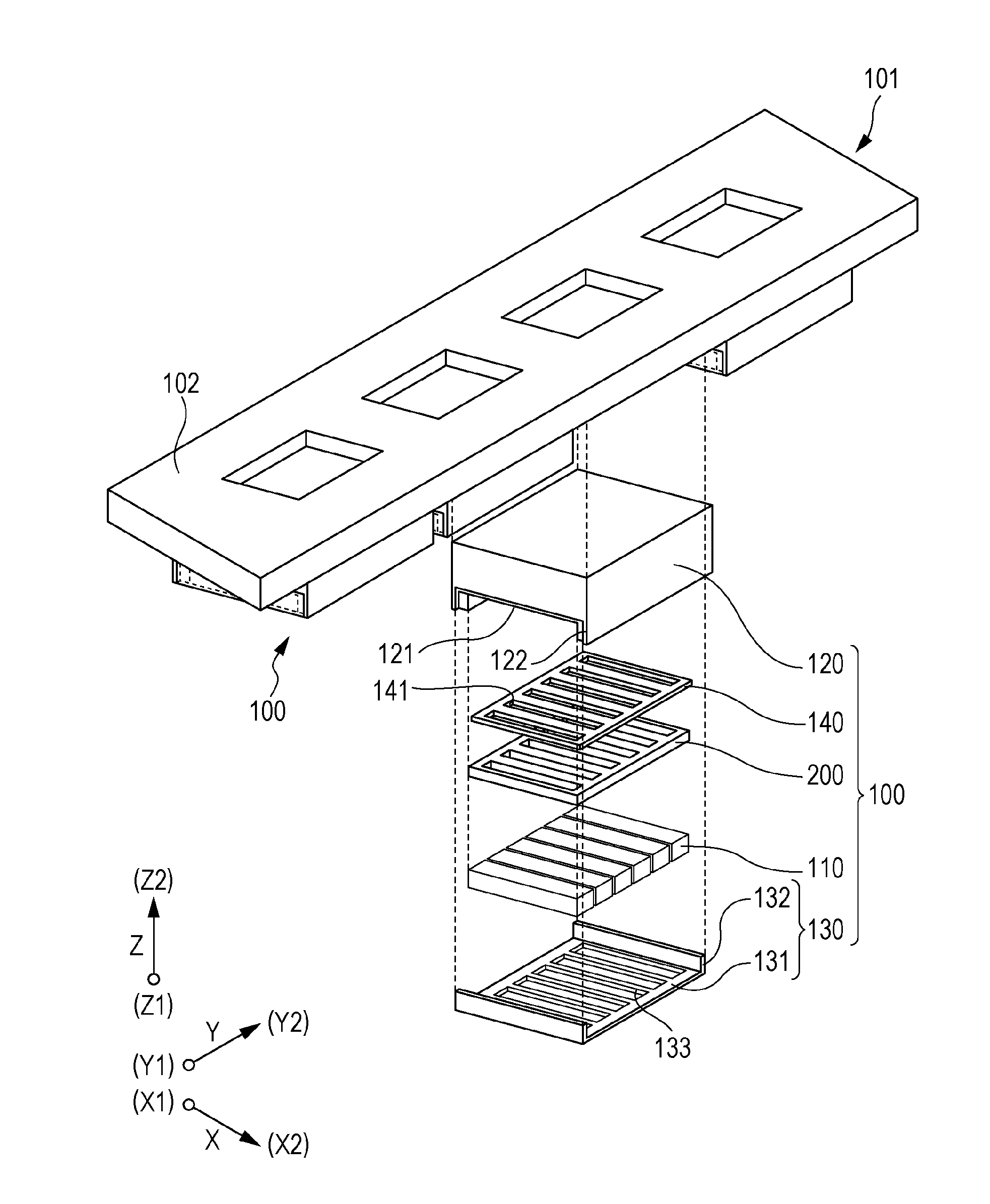
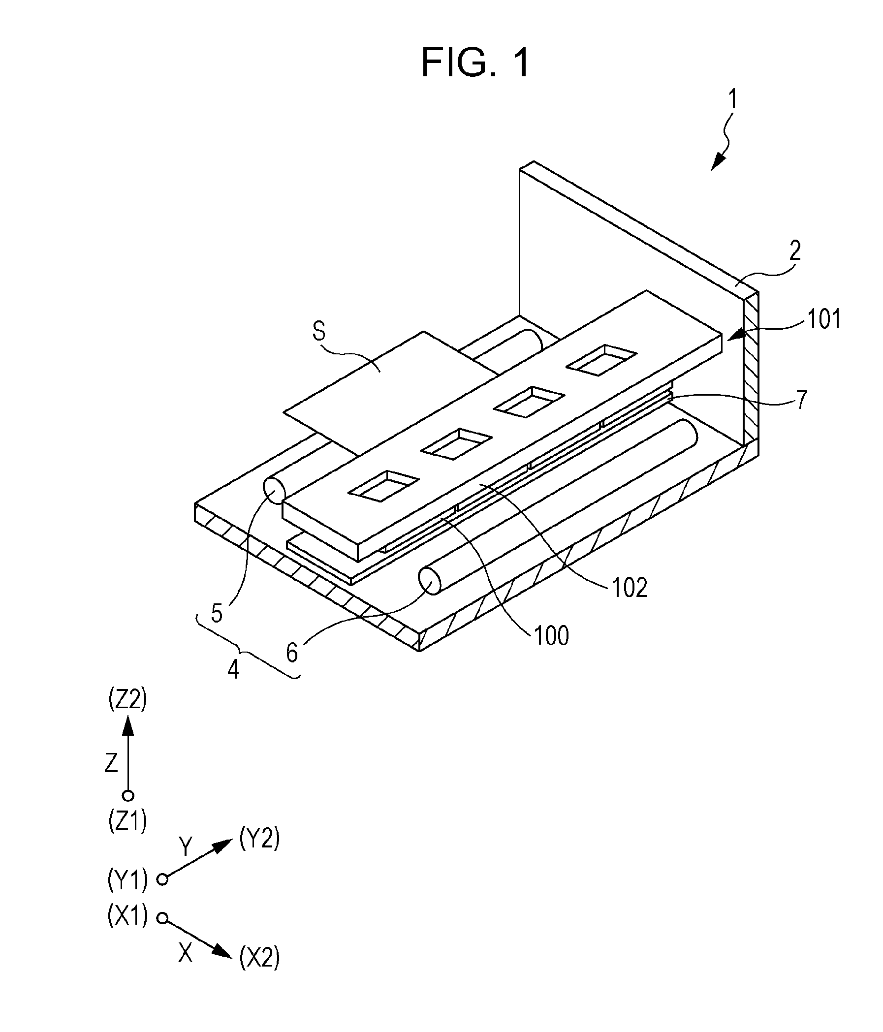
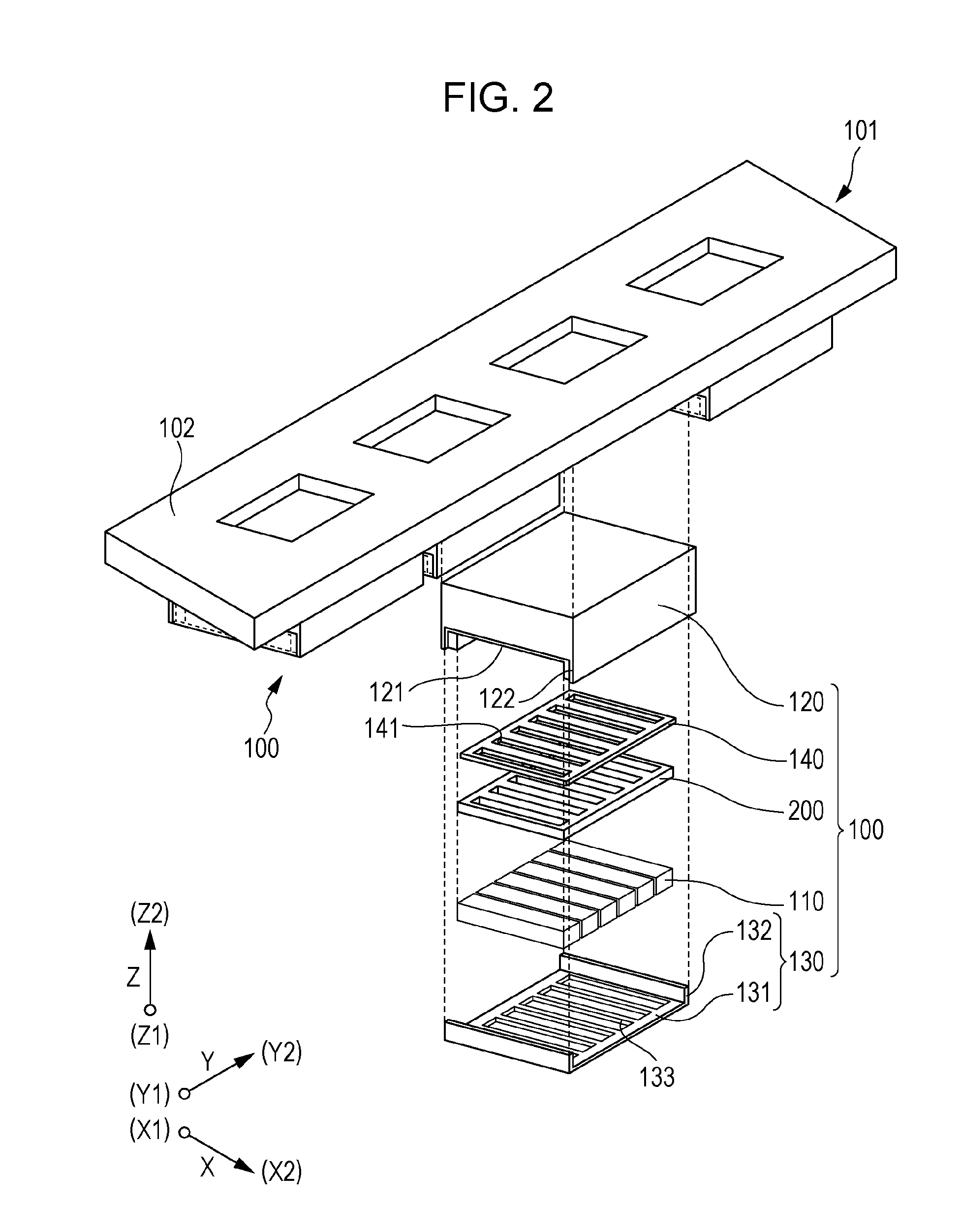
[0055]Details of embodiments of the invention will be described. An ink jet type recording head is an example of a liquid ejecting head and also referred to simply as a recording head. An ink jet type recording unit is an example of a liquid ejecting head unit and also referred to simply as a head unit. An ink jet type recording apparatus is an example of a liquid ejecting apparatus. FIG. 1 is a perspective view illustrating the schematic configuration of an ink jet type recording apparatus according to this embodiment.

[0056]An ink jet type recording apparatus 1 is a so-called line type recording apparatus, as illustrated in FIG. 1. The ink jet type recording apparatus 1 includes a head unit 101. In the ink jet type recording apparatus 1, a recording sheet S, such as a paper sheet as an ejection target medium, is transported, in such a manner that printing is performed.

[0057]Specifically, the ink jet type recording apparatus includes an apparatus main body 2, the head unit 101, a tr...

embodiment 2

[0220]In the embodiment described above, pressure-loss adjustment is performed in each tributary portion of the vertical flow path 270. However, the bifurcation flow path 260 may have a structure capable of performing pressure-loss adjustment. The other members have the same configuration as those of the members of the embodiment described above. Thus, descriptions thereof will not be repeated.

[0221]Here, details of a connection portion between the bifurcation flow path 260 and the vertical flow path 270 will be described with reference to FIG. 23.

[0222]The bifurcation flow path 260 extends in a direction intersecting the vertical flow path 270 extending in the vertical direction. In this embodiment, the bifurcation flow path 260 extends in a surface parallel to the liquid ejection surface 20a. In a case where a portion in which the extended flow path of the bifurcation flow path 260 intersects the extended flow path of the vertical flow path 270 is set to the connection portion 275...


PUM


Abstract

A flow-path member has a flow path to supply liquid to each head main body having nozzle openings through which liquid is ejected. The flow path of the flow-path member includes a mainstream portion and a plurality of tributary portions which branch off from the mainstream portion. Each of the plurality of tributary portions includes a vertical flow path which is connected, on an outlet port side, to a manifold portion of the head main body. Furthermore, in the vertical flow path, the cross-sectional area changes in the middle thereof. In addition, in the respective vertical flow paths, positions at which the cross-sectional areas change are different from each other.

Description

CROSS REFERENCES TO RELATED APPLICATIONS[0001]This application claims priority to Japanese Patent Application No. 2014-056181 filed on Mar. 19, 2014. The entire disclosure of Japanese Patent Application No. 2014-056181 is hereby incorporated herein by reference.BACKGROUND[0002]1. Technical Field[0003]The present invention relates to a liquid ejecting head in which liquid is ejected from nozzle openings and a liquid ejecting apparatus.[0004]2. Related Art[0005]An ink jet type recording head which includes a head main body in which a pressure generation chamber communicating with a nozzle opening through which ink droplets are discharged is deformed by a pressure generation unit, such as a piezoelectric element, in such a manner that ink droplet is discharged through the nozzle opening and a flow-path member which constitutes a flow path of ink supplied to the head main body is known as a liquid ejecting head.[0006]In a case where a plurality of tributary flow paths which communicate,...

Claims


Application Information

Patent Timeline
Patent Type & Authority Applications(United States)
IPC IPC(8): B41J2/14
CPCB41J2/1433B41J2/14233B41J2002/14362B41J2002/14419B41J2002/14491B41J2202/20B41J2/14145B41J2002/14306
Inventor YOSHIDA, AYUMI
Owner SEIKO EPSON CORP
Why Eureka
Try Eureka