Alignment Apparatus

Active Publication Date: 2014-01-23
OPTOS PLC
View PDF3 Cites 23 Cited by
  • Summary
  • Abstract
  • Description
  • Claims
  • Application Information

AI Technical Summary

Benefits of technology

The patent describes an apparatus and method for aligning an ophthalmic or optometric instrument with a patient's eye. The apparatus includes a camera to image the eye, a processor to determine the eye position, and a display to show a first graphical object representing an ideal eye position and a second graphical object representing the actual eye position. The processor can use edge detection algorithms to identify the center point of the pupil and can also overlay the first and second graphical objects on the eye image. The method involves positioning the eye, imaging it with a camera, and analyzing the image data to determine the eye position. The apparatus and method can be used to align the instrument with the eye for examination.

Problems solved by technology

This is particularly important for diagnostic applications where in-focus images of the retina or other parts of the eye are required, and where incorrect positioning of the eye can cause a resulting diagnosis to be unreliable, or for features to be mis-characterized or altogether unseen by an operator of the equipment.
However, the x and y alignment mechanism can be difficult to use, because it relies upon making an alignment of two ellipses; and the z-alignment mechanism provides only a coarse indication of the actual eye position.
For all these systems, when a patient's eye is not in an ideal position, it is difficult for an operator of the equipment to ascertain quickly and intuitively which correctional motion is required in order to bring the eye into the correct position.
This lack of intuition slows down the eye examination and can increase the likelihood of the operator making errors, in particular in cases where the patient's eye position moves away from an ideal position during the use of the apparatus.

Method used


Image

  • Alignment Apparatus
  • Alignment Apparatus
  • Alignment Apparatus

Examples


Embodiment Construction

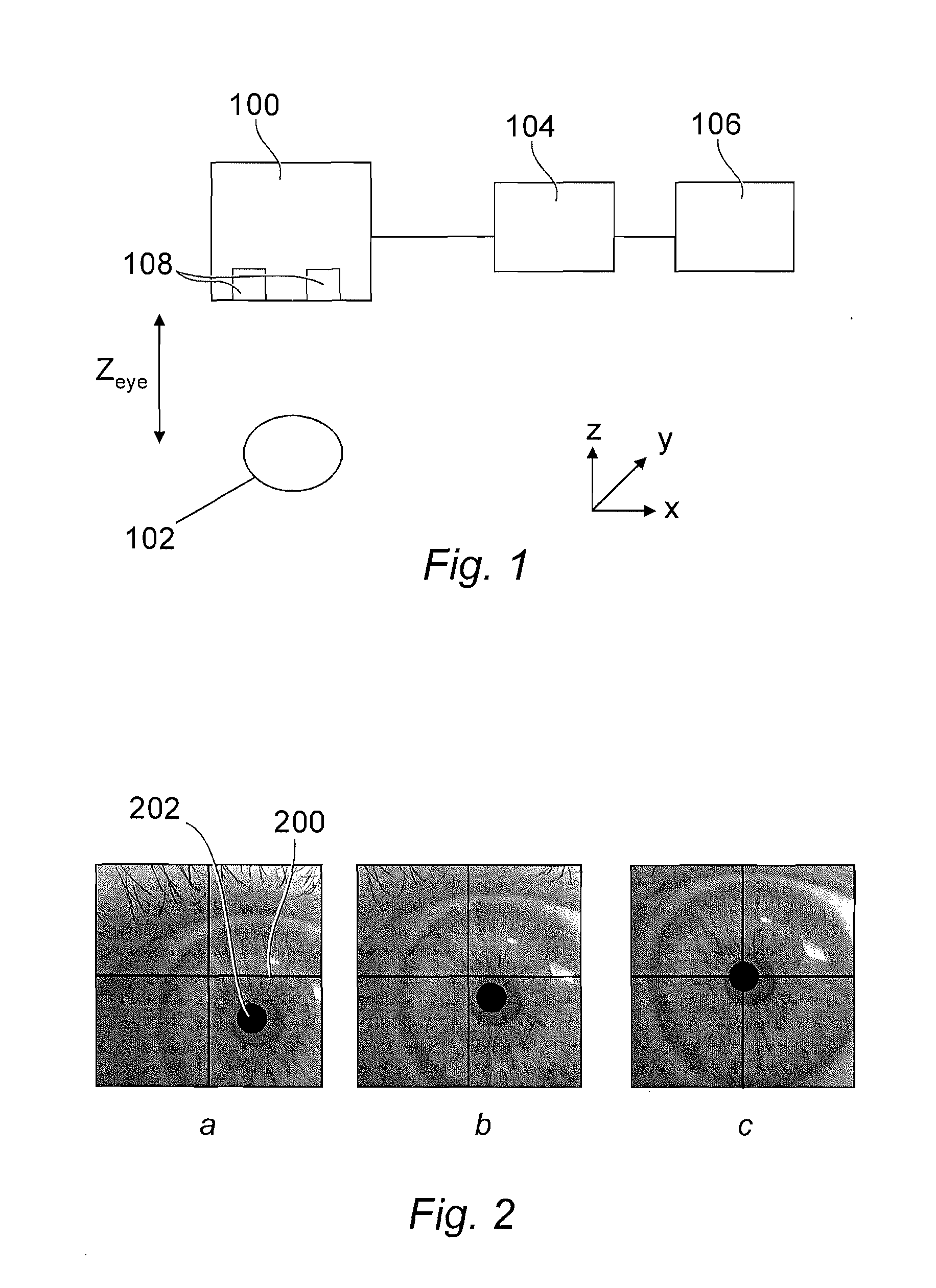
[0051]FIG. 1 illustrates an ophthalmic or optometric apparatus. An instrument 100 is provided for examination of a patient's eye 102. The instrument 100 is coupled with a processor 104, which may be an integral part of the instrument 100 or provided as (or as part of) a separate computer such as a personal computer. The processor 104 provides control signals for forming images on a display 106. Again the display 106 may be an integral part of the instrument 100 or part of a separate computer coupled with the instrument 100. The processor also receives data from the instrument 100, as described below.

[0052]The instrument 100 is used by an operator, being a different person from the person under examination and whose eye 102 is being imaged. The operator may be an eye care professional with suitable training and / or qualifications such as an ophthalmologist, orthoptist, optometrist or nurse; or a trainee or assistant under the supervision of such a person.

[0053]Various peripherals may ...


PUM


Abstract

An alignment apparatus and method is disclosed, for ensuring correct alignment of a patient's eye with respect to an ophthalmic or optometric instrument. Graphical objects are provided which represent an ideal and an actual position of the eye, and provide for easy and intuitive feedback to an eye care professional operating the instrument on the alignment position of the patient.

Description

FIELD OF THE INVENTION[0001]The present disclosure relates to an alignment apparatus and associated method, particularly but not exclusively for aligning an eye for examination by an ophthalmic or optometric instrument.DESCRIPTION OF THE RELATED ART[0002]Examples of ophthalmic or optometric instruments include ophthalmoscopes, scanning laser ophthalmoscopes, slit lamps, fundus cameras and so on.[0003]Fundus cameras comprise microscopes with attached cameras for photographing the interior surface of the eye including the retina, optic disc, macula and fundus. They may use various ophthalmoscopy techniques and image processing techniques such as optical coherence tomography (OCT).[0004]In general, it is important that a patient's eye is correctly positioned in the relevant apparatus. This is particularly important for diagnostic applications where in-focus images of the retina or other parts of the eye are required, and where incorrect positioning of the eye can cause a resulting diag...

Claims


Application Information

Patent Timeline
IPC IPC(8): G09G5/02H04N13/02G09G5/00H04N7/18
CPCA61B3/12A61B3/113
Inventor RICE-JONES, JENNIFER MARGARETBARTELME, MICHAEL JAMES
Owner OPTOS PLC
Why Eureka
Try Eureka