LED lamp structure

Inactive Publication Date: 2014-01-23
YINGGUANG
View PDF5 Cites 3 Cited by
  • Summary
  • Abstract
  • Description
  • Claims
  • Application Information

AI Technical Summary

Benefits of technology

[0006]The present invention has been accomplished under the circumstances in view. It is main object of the present invention to pr

Problems solved by technology

In consequence, the fabrication of different sizes or configurations

Method used


Image

  • LED lamp structure
  • LED lamp structure
  • LED lamp structure

Examples


Embodiment Construction

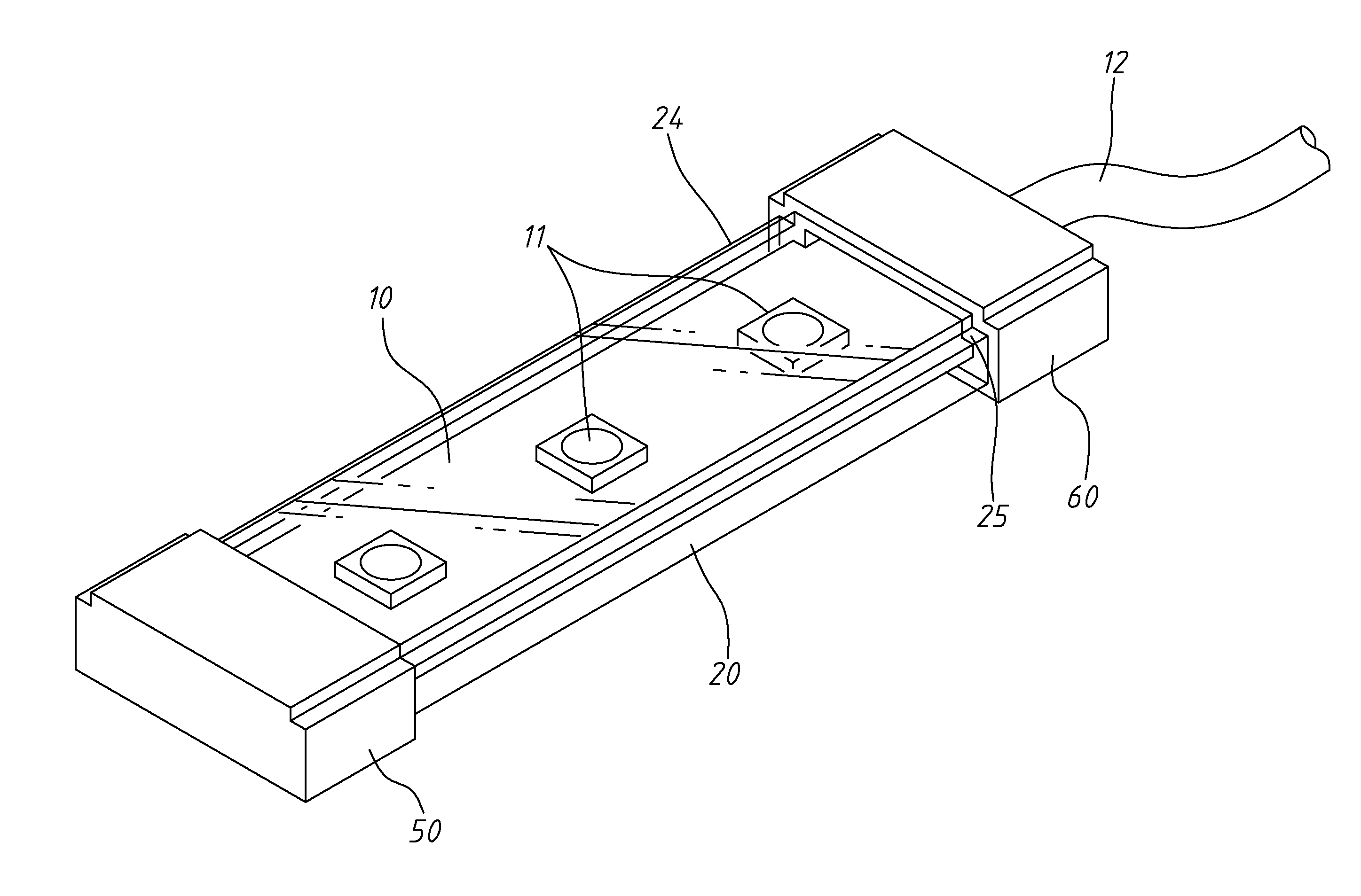
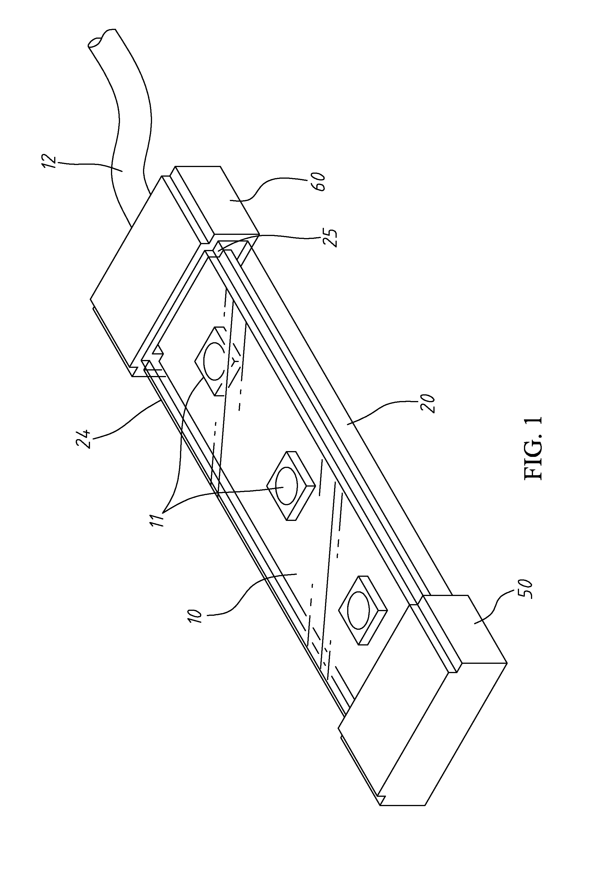
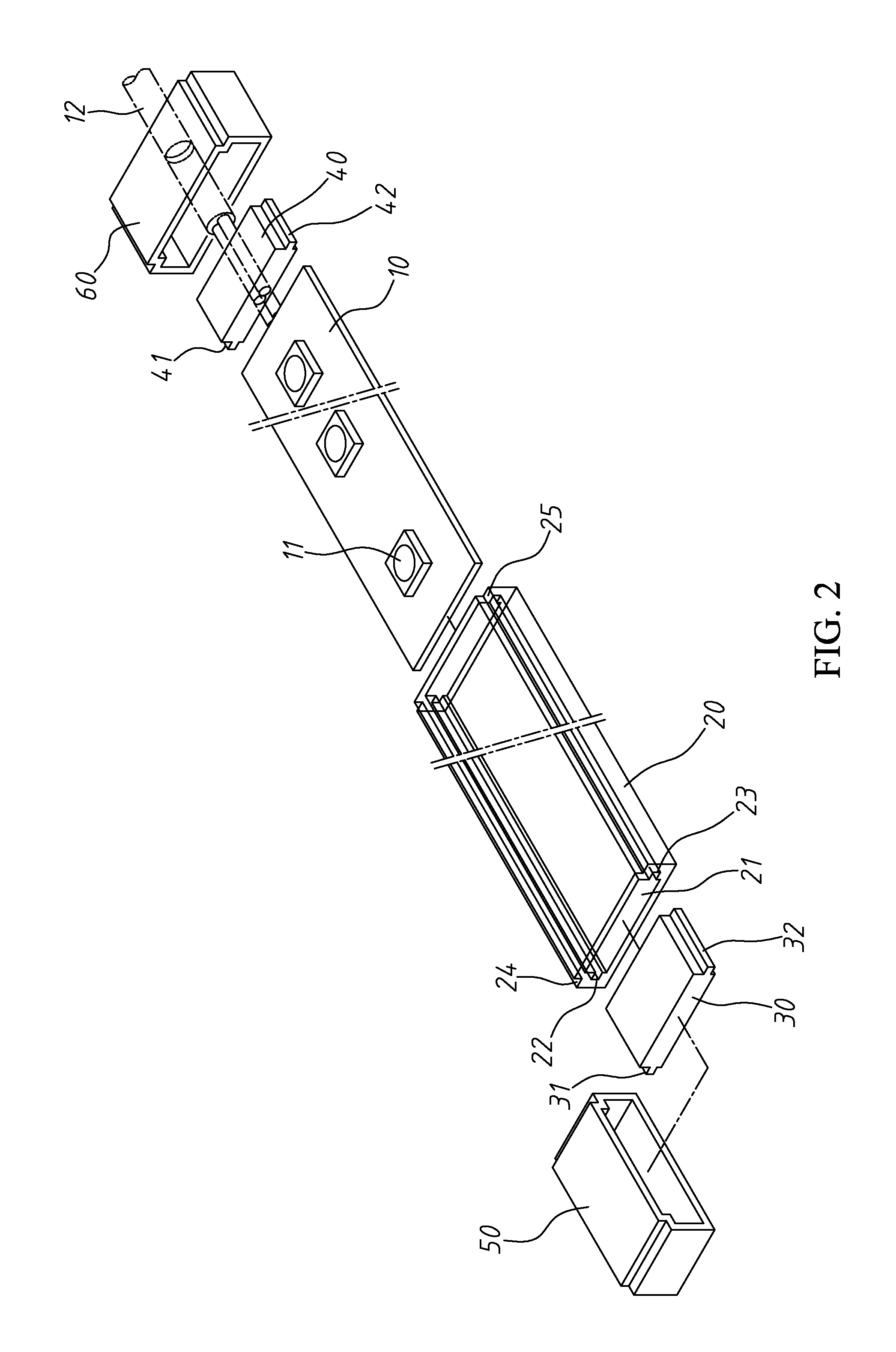
[0020]Referring to FIGS. 1 and 2, a LED lamp structure in accordance with the present invention generally is shown. The LED lamp structure comprises a circuit board 10 having a plurality of LEDs (light-emitting diodes) 11 mounted thereon by, for example, but not limited to, surface-mount technology; a power cable 12 extended from the circuit board 10 and electrically connectable to an external power source to obtain the necessary working voltage for the LEDs 11 at the circuit board 10; a housing20, which is made of a transparent material (for example, transparent plastics) and comprises an accommodation chamber 21 extending through opposing front and rear ends thereof and configured to accommodate the circuit board 10 and its LEDs 11, two longitudinal locating grooves 22;23 bilaterally disposed in the accommodation chamber 21 and configured subject to the wall thickness of the circuit board 10 and at least one, for example, two outside steps 24;25 bilaterally located on the outside ...


PUM


Abstract

A LED lamp structure includes a circuit board carrying multiple spaced LEDs and provided with a power cable, a single-piece housing cut from an integral tubular bar subject to the length of the circuit board and adapted to accommodate the circuit board, two end plugs respectively plugged into the two ends of the single-piece housing, and two end caps respectively capped on the two ends of the single-piece housing for enabling the power cable to extend to the outside of the single-piece housing for connection to an external power source.

Description

BACKGROUND OF THE INVENTION[0001]1. Field of the Invention[0002]The present invention relates LED lighting technology and more particularly, to a LED lamp structure, which allows the use of same component parts to make different lengths and configurations of LED lamps.[0003]2. Description of the Related Art[0004]In the early days since the creation of semiconductor light source, LEDs can simply give off low-intensity red light. Single-color LEDs were developed a certain period of time after the creation of semiconductor light source. Nowadays, modern designs of LEDs are available across the visible, ultraviolet, and infrared wavelengths, with very high brightness. LEDs are used in applications as aviation lighting, automotive lighting, advertising, general lighting and traffic signals. LEDs prevent many advantages over conventional incandescent light sources, including lower energy consumption, longer lifetime, longer durability, smaller size, and faster switching.[0005]However, for...

Claims


Application Information

Patent Timeline
IPC IPC(8): F21V15/01
CPCF21V15/01F21S4/28F21Y2103/10F21Y2115/10
Inventor WANG, YU-CHIN
Owner YINGGUANG
Why Eureka
Try Eureka