Pedal effort generation device for vehicle

a technology of pedal effort and generation device, which is applied in the direction of mechanical control devices, gearing, instruments, etc., can solve the problems of high manufacturing cost, high installation cost, and gradual increase of the pedal effort of the driver's foot, so as to improve the oper save the manufacturing cost of the pedal unit, and improve the marketability of the pedal unit

Active Publication Date: 2019-11-19
HYUNDAI MOTOR CO LTD +1
View PDF10 Cites 0 Cited by
  • Summary
  • Abstract
  • Description
  • Claims
  • Application Information

AI Technical Summary

Benefits of technology

[0031]According to embodiments of the present disclosure, the best pedal effort can be generated with the simple configuration including the connection link, the rotating cylinder, and the geometry slot, thereby saving the manufacturing costs of the pedal unit and improving the operability of the pedal unit.
[0032]In addition, according to embodiments of the present disclosure, the pedal effort profile can be simply changed according to the driver's preference by variously modifying the motion of the geometry slot provided in the rotating cylinder, thereby improving the marketability of the pedal unit and providing a customizable pedal only by the replacement of the rotating cylinder.

Problems solved by technology

As an example, if a driver steps on the pedal slowly, the driver's foot experiences a gradually increasing pedal effort as the pedal rotates.
However, since the structure of the pedal device needs to be changed to change the pedal effort profile, such an installation can be costly.
However, since the conventional active pedal devices use expensive components, manufacturing costs are often high, and marketability may deteriorate as the pedal effort profile deteriorates over time.

Method used


Image

  • Pedal effort generation device for vehicle
  • Pedal effort generation device for vehicle
  • Pedal effort generation device for vehicle

Examples


Embodiment Construction

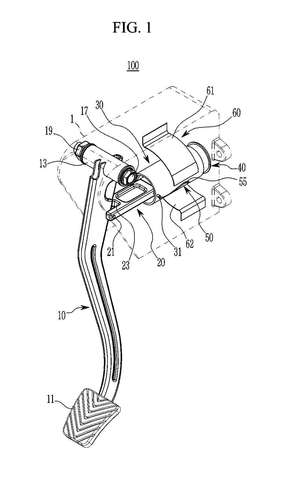
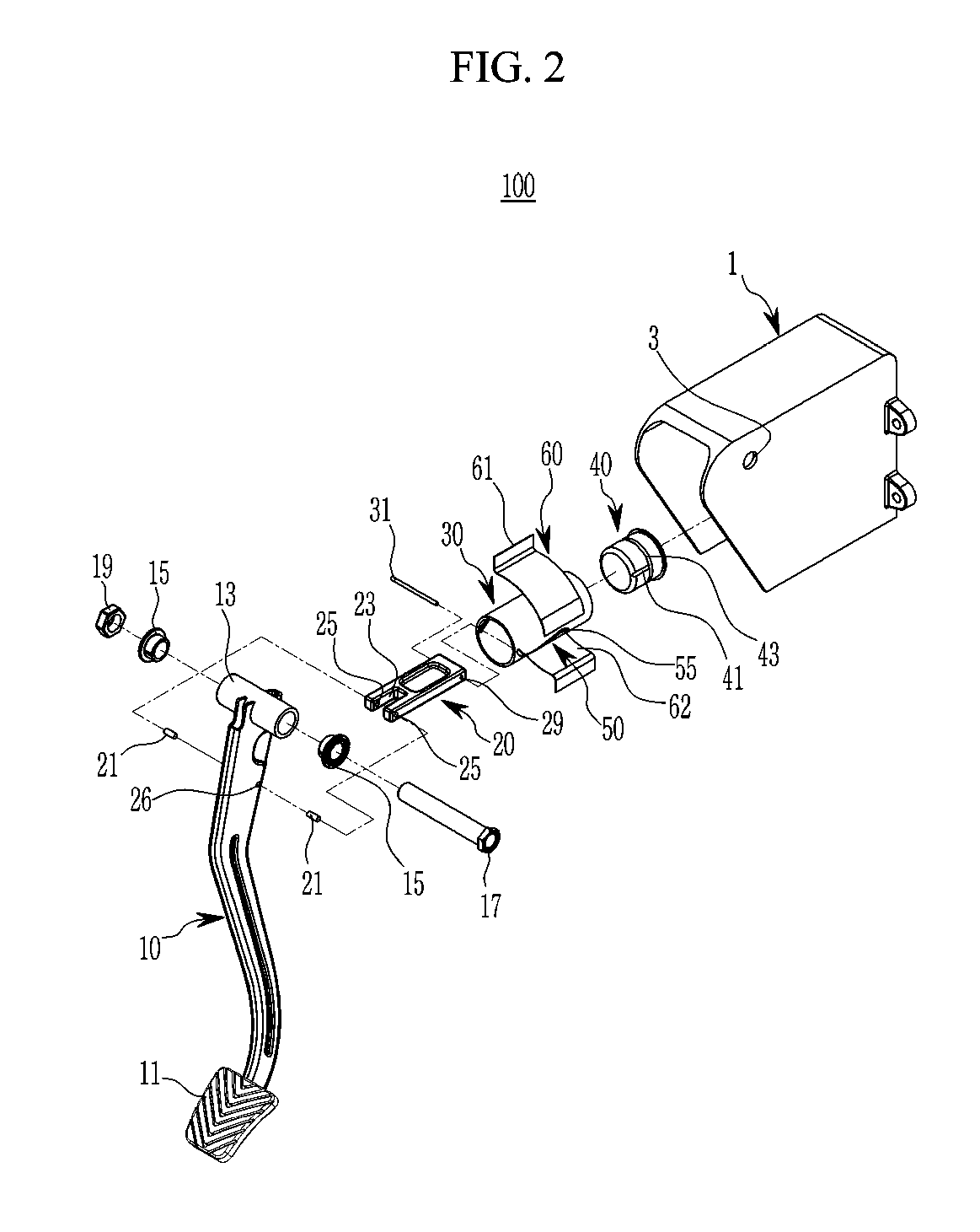
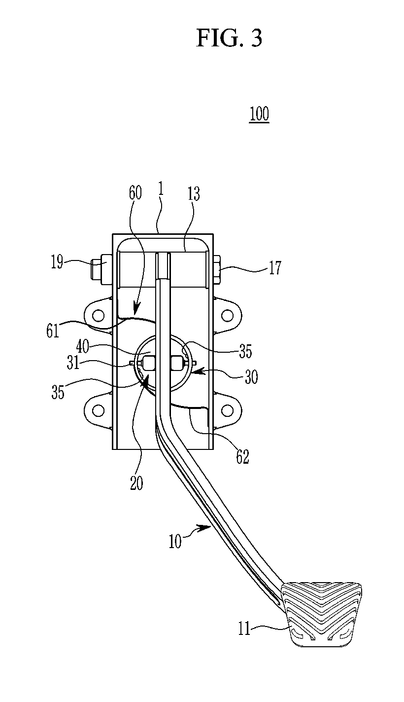
[0059]Hereinafter, the present disclosure will be described more fully hereinafter with reference to the accompanying drawings, in which embodiments of the disclosure are shown. As those skilled in the art would realize, the described embodiments may be modified in various different ways, all without departing from the spirit or scope of the present disclosure.

[0060]Accordingly, the drawings and description are to be regarded as illustrative in nature and not restrictive. Like reference numerals designate like elements throughout the specification.

[0061]However, since sizes and thicknesses of the respective components were arbitrarily shown in the accompanying drawings for convenience of explanation, the present disclosure is not necessarily limited to contents shown in the accompanying drawings. In addition, thicknesses were exaggerated in order to obviously represent several portions and regions.

[0062]In the following detailed description, the same components are classified into f...


PUM


Abstract

A pedal effort generation device for a vehicle includes: a pedal arm rotatably mounted on a pedal member in a front and rear direction; a connection link having one end at a rear side of the connection link hinged to the pedal arm; a rotating cylinder connected with the other end of the connection link and rotatably mounted on the pedal member; a follower unit mounted on the rotating cylinder, slidably coupled to the other end of the connection link, and configured to convert linear motion of the connection link into rotational motion of the rotating cylinder according to a front rotation of the pedal arm; and an elastic mechanism connected with the pedal member and the rotating cylinder, elastically deformed upon a forward rotation of the rotating cylinder according to the front rotation of the pedal arm, and configured to provide a reverse restoring force to the rotating cylinder and the pedal arm with an accumulated elastic force.

Description

CROSS-REFERENCE TO RELATED APPLICATION[0001]This application claims the benefit of priority to Korean Patent Application No. 10-2017-0143288 filed in the Korean Intellectual Property Office on Oct. 31, 2017, the entire contents of which are incorporated herein by reference.BACKGROUND OF THE DISCLOSURE[0002](a) Technical Field[0003]Embodiments of the present disclosure relate generally to a pedal system for a vehicle, and more particularly, to a pedal effort generation device for a vehicle capable of implementing a best pedal effort.[0004](b) Description of the Related Art[0005]Generally, vehicles are provided with various types of pedals such as a brake pedal, an accelerator pedal, and a clutch pedal. The pedals are operated by a driver while the vehicle is running to change a running condition of the vehicle. Therefore, the pedal is directly linked with safety of the driver or of pedestrians.[0006]The pedals are operated by the driver's foot, such that the driver may feel pedal eff...

Claims


Application Information

Patent Timeline
Patent Type & Authority Patents(United States)
IPC IPC(8): G05G5/03F16H25/18B60T7/04B60K23/02G05G1/44F16F1/18
CPCB60T7/042G05G5/03G05G1/44F16H25/186B60K23/02F16F1/18G05G2505/00B60Y2400/3012G05G1/30G05G5/05
Inventor KIM, EUN SIK
Owner HYUNDAI MOTOR CO LTD
Why Eureka
Try Eureka