Bolt joining method and tools therefor

a bolt and jointing technology, applied in auxillary welding devices, programmatic control, instruments, etc., can solve problems such as workpiece damage and insufficient strength of joints, and achieve the effect of avoiding interference between bushings adjacent to the transponder

Inactive Publication Date: 2014-01-23
NEWFREY
View PDF16 Cites 16 Cited by
  • Summary
  • Abstract
  • Description
  • Claims
  • Application Information

AI Technical Summary

Benefits of technology

[0012]As a result of the measure of arranging an RFID transponder in the region of the position of the operating step to be carried out, in which RFID transponder the parameter value or a number of a set of joining parameters or the like for this position is stored, this parameter value can be read out by means of the RFID communication device when the tool is placed in the region of the position. As a result, it is possible to automatically set the tool or other devices with reference to the parameter value, such that a manual selection of the parameter value is dispensed with. This can ensure that the correct parameter value can be used for the respective working step to be carried out. Incorrect working steps on account of the selection of an incorrect parameter value can be avoided in this way.
[0045]Furthermore, it is preferred in this case if the bushing has an outer sleeve and an inner ring connected thereto, wherein the RFID transponder is integrated into the inner ring. The outer sleeve of the bushing is preferably made of a metallic material and can therefore be secured to the positioning device (template) by conventional joining methods. The inner ring preferably has a non-conductive and non-magnetic material, such as, for example, plastic or synthetic resin. Owing to the fact that the outer sleeve surrounds the inner ring, interference between bushings adjacent to the transponder can be avoided. Furthermore, the outer sleeve can remain on the template, even if the RFID transponder is exchanged.

Problems solved by technology

Errors can occur during the manual selection, and therefore the incorrect joining parameters are selected for the respective joining process.
This may lead to the joint not having the adequate strength, to the workpiece being damaged, etc.

Method used


Image

  • Bolt joining method and tools therefor
  • Bolt joining method and tools therefor
  • Bolt joining method and tools therefor

Examples


Embodiment Construction

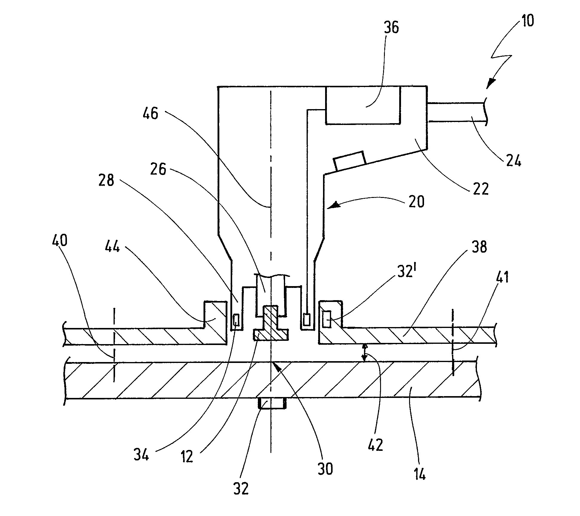
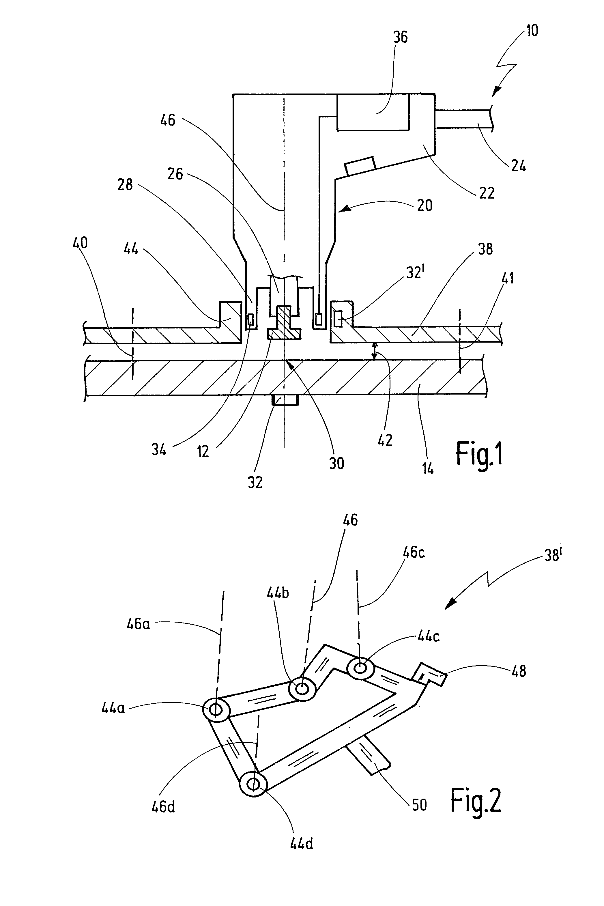
[0053]A joining arrangement in the form of a stud welding arrangement is designated generally by 10 in FIG. 1. The joining arrangement 10 serves to join a stud 12 to a workpiece 14 in the form of a sheet or the like in one working step. The joining operation is effected in this case preferably in such a way that an integral connection, such as a welded or adhesively bonded connection, is set up between the stud 12 and the workpiece 14. The joining operation is carried out only from one side of the workpiece 14.

[0054]The joining arrangement 10 has a joining tool 20 in the form of a stud welding gun. The joining tool 20 has a handle 22 and is connected via a schematically indicated supply line 24 to a power source and possibly to a control device.

[0055]In the region of a head, the joining tool 20 has a holding device 26 for holding a stud 12. The holding device 26 is surrounded by a mouthpiece 28, which can be connected, for example, rigidly to the housing of the joining tool 20. The ...


PUM

PropertyMeasurementUnit
thicknessesaaaaaaaaaa
voltageaaaaaaaaaa
currentaaaaaaaaaa

Abstract

A method for carrying out a stud joining process by a tool performing a working step on a workpiece and the working step is carried out while taking into account at least one parameter value which is selected from a set of values, and the working step is to be carried out at a certain position on the workpiece, and the position determines the parameter value. The method comprises the steps of: storing the parameter value for the position in an RFID transponder; locating the RFID transponder on the workpiece in the region of the position before the working step is carried out, reading the parameter value out from the RFID transponder with an RFID communication device associated with the tool.

Description

CROSS-REFERENCE TO RELATED APPLICATIONS[0001]This application is a continuation of PCT Application No. PCT / EP2012 / 050587, filed on Jan. 17, 2012 which claims priority from German Patent Application No. DE 102011016132.5, filed on Mar. 29, 2011, the disclosure of which is incorporated herein by reference.BACKGROUND OF THE INVENTION[0002]The present invention relates to a workpiece processing method for carrying out a working step on a workpiece by means of a tool, in particular for carrying out a stud joining process, wherein the working step is carried out while taking into account at least one parameter value which is selected from a set of values, and wherein the working step is to be carried out at a certain position on the workpiece, said position determining the parameter value.[0003]Furthermore, the present invention relates to a tool for carrying out such a method, in particular a stud joining tool, and to a positioning device for carrying out this method.[0004]In workpiece p...

Claims


Application Information

Patent Timeline
Patent Type & Authority Applications(United States)
IPC IPC(8): G05B19/402
CPCB23K9/202B23K11/0053G05B19/402B23K37/0426B23K37/0217
Inventor HAIN, JOCHENSCHMIDT, FRANK
Owner NEWFREY
Why Eureka
Try Eureka