Tobacco head for a water pipe

a technology of tobacco head and water pipe, applied in the field of tobacco head, to achieve the effect of less easily destroyed in operation

Inactive Publication Date: 2014-01-30
DABES IBRAHIM
View PDF12 Cites 12 Cited by
  • Summary
  • Abstract
  • Description
  • Claims
  • Application Information

AI Technical Summary

Benefits of technology

[0008]There is therefore the problem of improving a tobacco head for a water pipe in such a manner that it is less easily destroyed in operation and during the cleaning process.

Problems solved by technology

There is therefore the problem of improving a tobacco head for a water pipe in such a manner that it is less easily destroyed in operation and during the cleaning process.

Method used


Image

  • Tobacco head for a water pipe
  • Tobacco head for a water pipe

Examples


Embodiment Construction

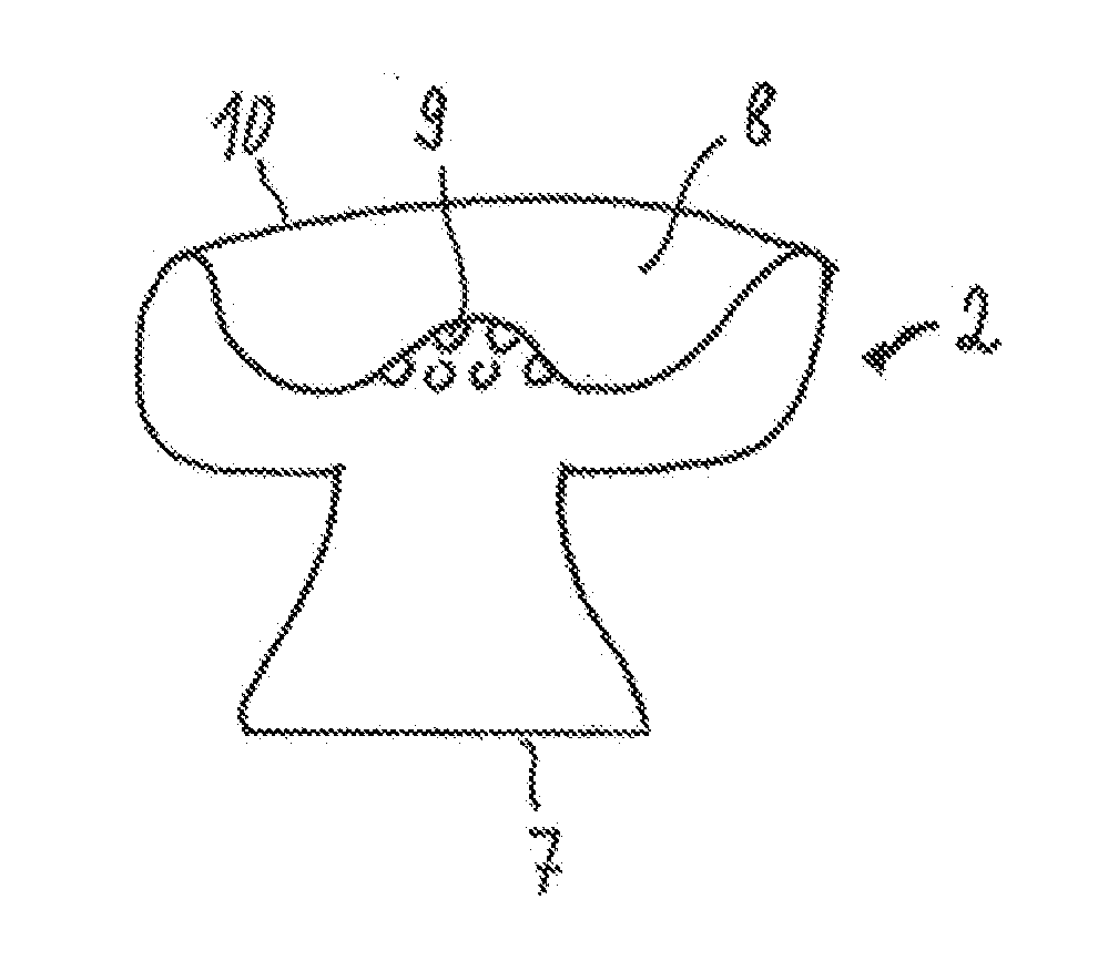
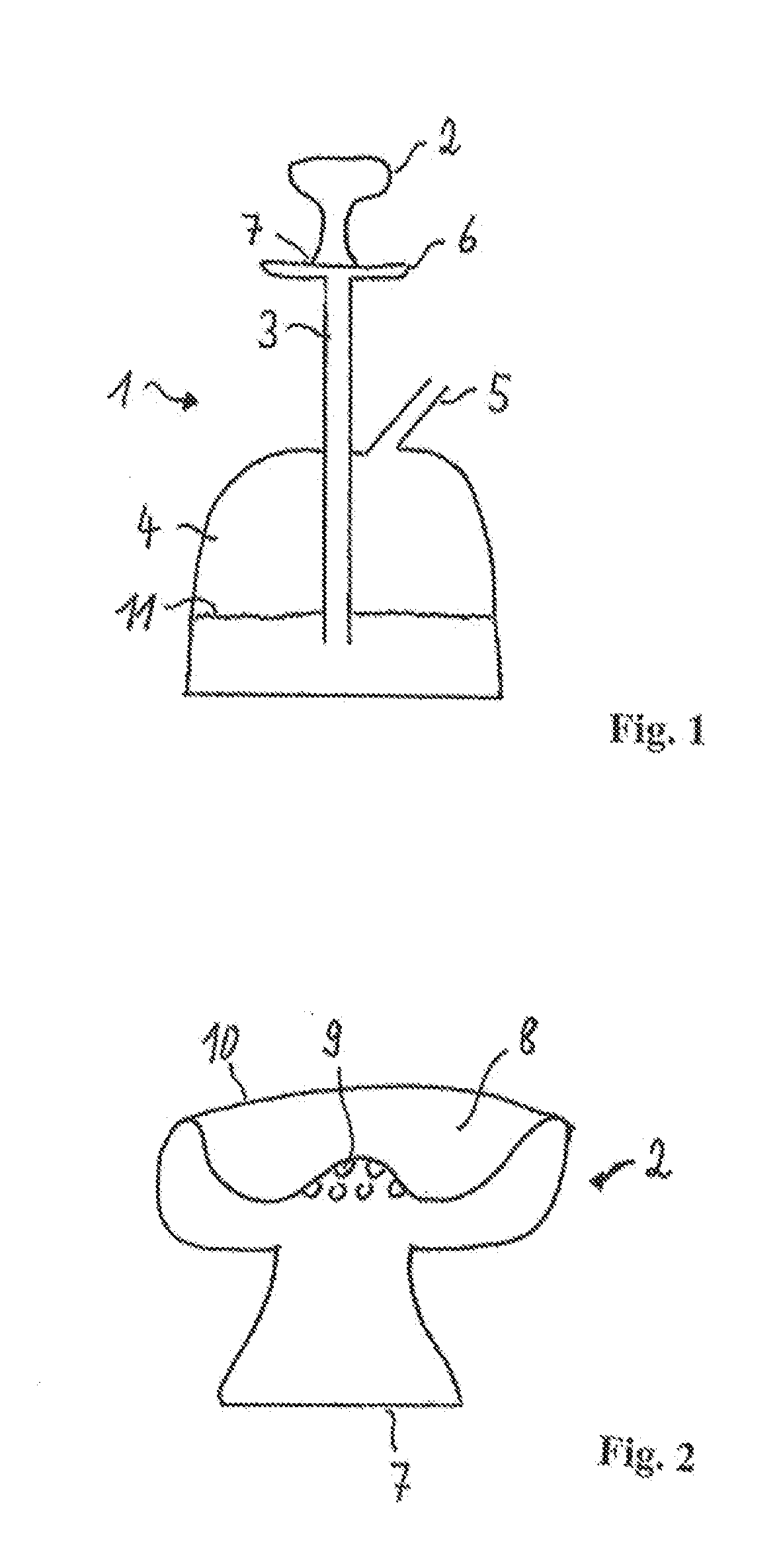
[0013]As shown in FIG. 1, the water pipe 1 has a body tube 3, which is connected at its lower end to a water container 4 and extends under the water surface 11 inside the container 4. The body tube 3 further comprises a hose fitting 5, to which a hose, supporting a mouthpiece for the user at its other end, can be attached.

[0014]On its top side, with an intermediate plate 6, the body tube 3 has the actual tobacco head 2, which can be inserted on its underside 7 into the body tube 3 and has a pot-shaped recess 8 for holding the tobacco on its upper side. The bottom of this pot-shaped recess 8 is provided with holes 9 for passing the tobacco vapors downward into the body tube 3. A perforated foil, a screen or another permeable material, on which the heating medium such as charcoal is located, can be clipped over the upper side 10 of the recess 8.

[0015]The geometric design of the tobacco head is conventionally known.

[0016]According to the invention, however, the tobacco head 2 does not ...


PUM


Abstract

The invention relates to a tobacco head for a water pipe. Known tobacco heads of this type break easily during cleaning or if the water pipe tips over. The problem of further developing such a tobacco head so that it is not destroyed so easily during the cleaning process is solved in that the tobacco head consists of a flexible elastically yielding material.

Description

CROSS REFERENCE TO RELATED APPLICATIONS[0001]This application claims priority under 35 U.S.C. §119 to German Patent Application No. DE 10 2012 106 919.0 filed 30 Jul. 2012, the entire contents of which are incorporated herein by reference.FIELD OF THE INVENTION[0002]The invention relates to a tobacco head (also known as a tobacco bowl) for a water pipe (also known as a hookah).BACKGROUND OF THE INVENTION[0003]The principle of a water pipe with a tobacco head (referred to there as a head) is explained in DE 20 2008 016 573 U1.[0004]In a water pipe, tobacco is heated by a hot medium, e.g. charcoal. The outflowing vapors are routed through a water bath, cooled and cleaned and smoked via a hose outlet. The schematic structure of a water pipe is the subject of the above-mentioned publication. It consists of a substantially vertical body tube, to the top of which a tobacco head is attached that receives both the heating medium (the hot coals) and the tobacco to be smoked. The lower end of...

Claims


Application Information

Patent Timeline
Patent Type & Authority Applications(United States)
IPC IPC(8): A24F5/00
CPCA24F5/00A24F1/30
Inventor DABES, IBRAHIM
Owner DABES IBRAHIM
Why Eureka
Try Eureka