Gun locking device

a locking device and gun technology, applied in the field of guns and firearms, can solve the problems of ineffectiveness, difficult installation, easy disassembly and installation, etc., and achieve the effects of not being easily disarmed or destroyed, being easy to manufacture, and being convenient to us

Inactive Publication Date: 2017-08-24
OCHOA PHILIP
View PDF0 Cites 8 Cited by
  • Summary
  • Abstract
  • Description
  • Claims
  • Application Information

AI Technical Summary

Benefits of technology

[0010]The present invention resides in a gun locking device which is relatively simple in manufacture and easy to use. When in operation, the gun locking device is disposed within the gun so as to not be easily disarmed or destroyed. Moreover, the gun locking device of the present invention enables the locked gun to be placed in its existing case, holder, holster or the like.

Problems solved by technology

Many of these, however, are ineffective as they can be easily disarmed, difficult to install, fail to prevent discharge of the gun when installed, or overly complex in construction and expensive.
One problem with these types of locks is their safety is poor.
Consequently, it is easy to destroy the lock with a hacksaw, file or cutting pliers.
In addition, in the case of a handgun, it is difficult to put the handgun into a holster if it has an outside lock.
However, these are easily defeated as the cable can be accessed and cut with wire cutters or bolt cutters or the like.
Furthermore, the handgun is not able to be placed within a holster or the like when locked.
However, these lockable plugs also have disadvantages.
As the plugs often radially expand within the barrel and rely on frictional engagement with the inner wall of the barrel to resist removal of the plug from the barrel, they often require complex expanding mechanisms in order to achieve sufficient frictional contact between the barrel and the plug surfaces.
Moreover, while the plug is in the barrel, a substantial portion of their operating structure is usually exposed to tampering outside of the barrel.
The locking barrel plugs can also be difficult for the user to install and remove, and only offer modest resistance to unauthorized removal of the plug from the barrel.
They may also mar or more severely damage the barrel surface in normal use as their expanding components must exert significant force against the barrel wall.
What is also needed is a gun locking device which is not easily disarmed or removed from the gun.

Method used


Image

  • Gun locking device
  • Gun locking device
  • Gun locking device

Examples


Embodiment Construction

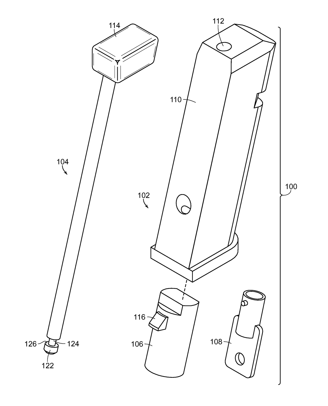
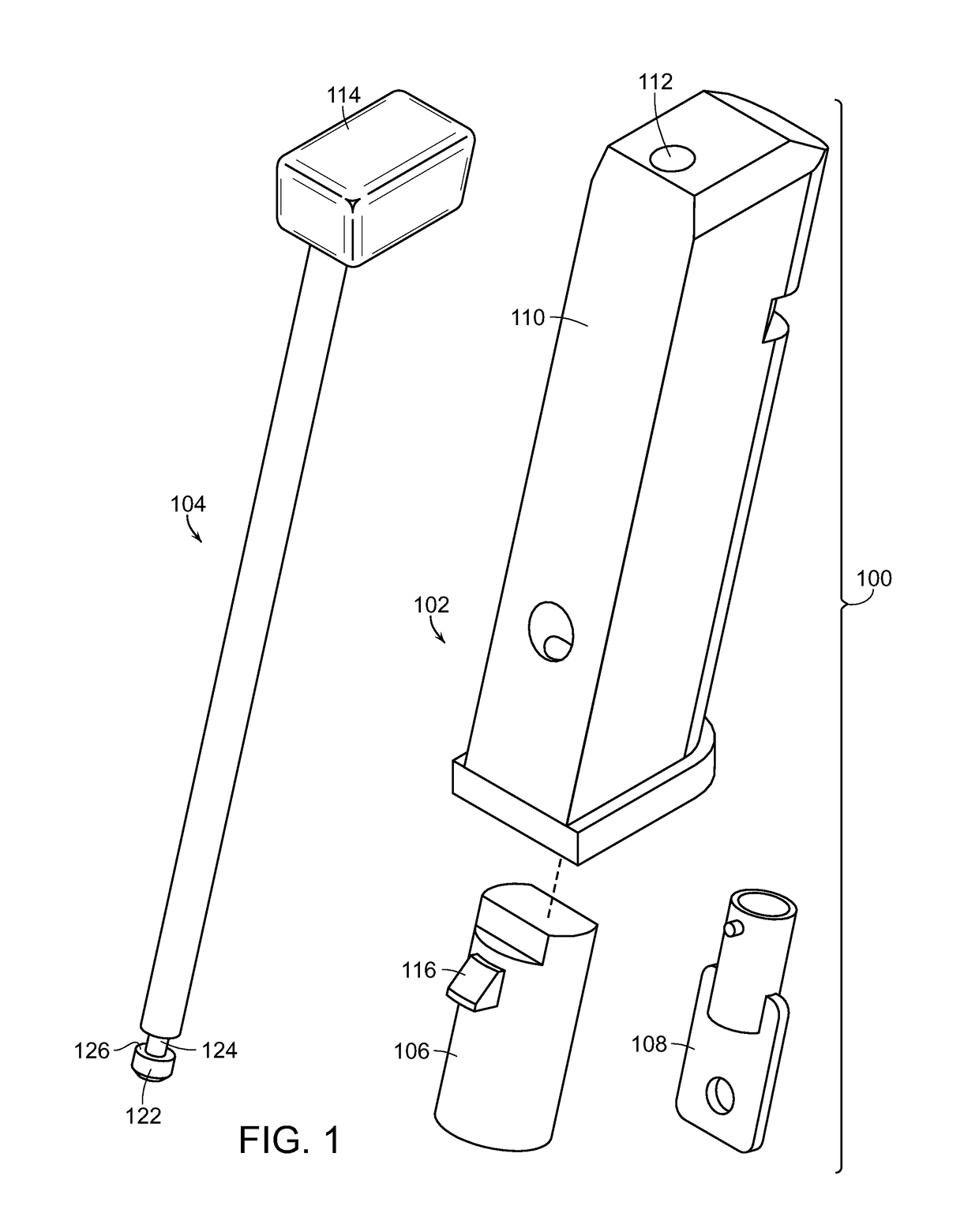
[0021]As shown in the accompanying illustrations for exemplary purposes, the present invention is directed to a gun locking device, generally referred to by the reference number 100. The device of the present invention is simple and easy to use and securely locks a firearm and prevents it from being loaded and discharged.

[0022]With reference to FIG. 1, the gun locking device 100 of the present invention generally comprises a lock assembly 102 which is removably disposable within a cavity of the gun. A rod 104, as will be more fully explained herein, extends through a chamber of the gun and is configured for locking engagement with a lock 106 of the locking assembly 102. The device 100 also includes a key 108, or other means for selectively unlocking the lock 106 to disengage the rod 104.

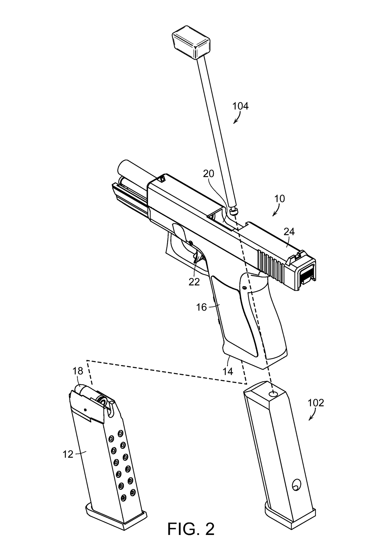
[0023]With reference now to FIG. 2, the present invention is particularly adapted for use in guns and firearms 10, such as the illustrated semi-automatic handgun, which utilize an ammunition magazine...


PUM


Abstract

A gun locking device includes a lock removably disposable within a cavity of a gun, such as being slidably received within a magazine well of the gun. An elongated rod is extendable into the gun through a chamber thereof for locking engagement with the lock. An end of the rod defines a plug disposable within the chamber of the gun when the rod is in engagement with the lock to prevent ammunition from being disposed within the chamber and the gun being discharged.

Description

RELATED APPLICATION[0001]This application claims priority to U.S. Provisional Application Ser. No. 62 / 233,744, filed Sep. 28, 2015.BACKGROUND OF THE INVENTION[0002]The present invention generally relates to guns and firearms. More particularly, the present invention relates to a gun locking device that prevents a gun from being loaded with ammunition and fired.[0003]Firearm use and ownership has increased over the years. Those owning and using guns include members of the military, police forces, and those owning guns ranging from the casual gun collector to those using guns for recreational or protective purposes.[0004]Along with the increased firearm ownership and use has come an enhanced concern for firearm safety. This includes a concern for preventing accidental discharge or unauthorized use of the gun.[0005]Safety devices have been introduced to address this concern. For example, there are various types of gun locks that are available. Many of these, however, are ineffective as...

Claims


Application Information

Patent Timeline
Patent Type & Authority Applications(United States)
IPC IPC(8): F41A17/44
CPCF41A17/44
Inventor OCHOA, PHILIP
Owner OCHOA PHILIP
Why Eureka
Try Eureka