Belt guide device for use in conveyor belts

a belt guide and belt technology, applied in the direction of conveyors, conveyor parts, transportation and packaging, etc., can solve the problems of belt pieces being torn off the edge, rubber strips formed by belt edges “unpeeling” and other problems, to achieve the effect of reducing the drawbacks

Inactive Publication Date: 2014-01-30
VALE LIMITED
View PDF9 Cites 1 Cited by
  • Summary
  • Abstract
  • Description
  • Claims
  • Application Information

AI Technical Summary

Benefits of technology

[0010]In light of the above, it is one of the objectives of the present invention to provide a belt guide device for use in conveyor belts that solves, or at least considerably diminishes, the drawbacks associated to the use of belt guide rollers.
[0011]It is another objective of the present invention to provide a belt guide device capable of preventing the formation of belt strips through contact between the belt and the roller, increasing the useful life of the belt and decreasing the risk of accidents caused by loose belt strips.
[0012]It is a further objective of the present invention to provide a belt guide device that decreases the need for constant replacement of the belt guide roller, increasing the operating efficiency and decreasing the risk of accidents associated to said maintenance or replacement.
[0013]It is yet another objective of the present invention to provide a belt guide device capable of decreasing the wear and tear of the surface of the belt guide roller.
[0014]It is still a further objective of the present invention to provide a belt guide device capable of decreasing the possibility of loss of the material transported by falling through the empty spaces left by strips torn off the belt.SUMMARY OF THE INVENTION
[0021]In the preferred embodiment of the present invention, the adjustment mechanism is a rod that extends longitudinally from one end of the sliding board, and the support track has a hollowed handle that enables the passage of the rod and assures its stability.

Problems solved by technology

In the case of guide rollers, this is especially true, since the edge of the belt may press the surface of the rollers with significant force, and even prevent movement thereof and cause pieces of belt to be torn off the edge.
Thus, there are at least two problems commonly associated to guide rollers: the heavy wear and tear of the surface of the guide roller in contact with the belt, and the formation of rubber strips by “unpeeling” of the edges of the belts.
These problems represent major operational drawbacks, since they decrease the useful life of the rollers—forcing constant replacements—and damage the belt of the conveyor.
Additionally, the “unpeeling” of the edges of the belts may cause the material transported to fall inadvertently through the gap formed where the rubber was torn, causing a significant operational loss.
Said known solutions, however, are merely palliative solutions that just treat the effects of the problem found in the use of conventional guide rollers, without solving the causes of the problem.

Method used


Image

  • Belt guide device for use in conveyor belts
  • Belt guide device for use in conveyor belts
  • Belt guide device for use in conveyor belts

Examples


Embodiment Construction

[0034]The present invention will now be described in greater detail based on an example of execution represented in the drawings.

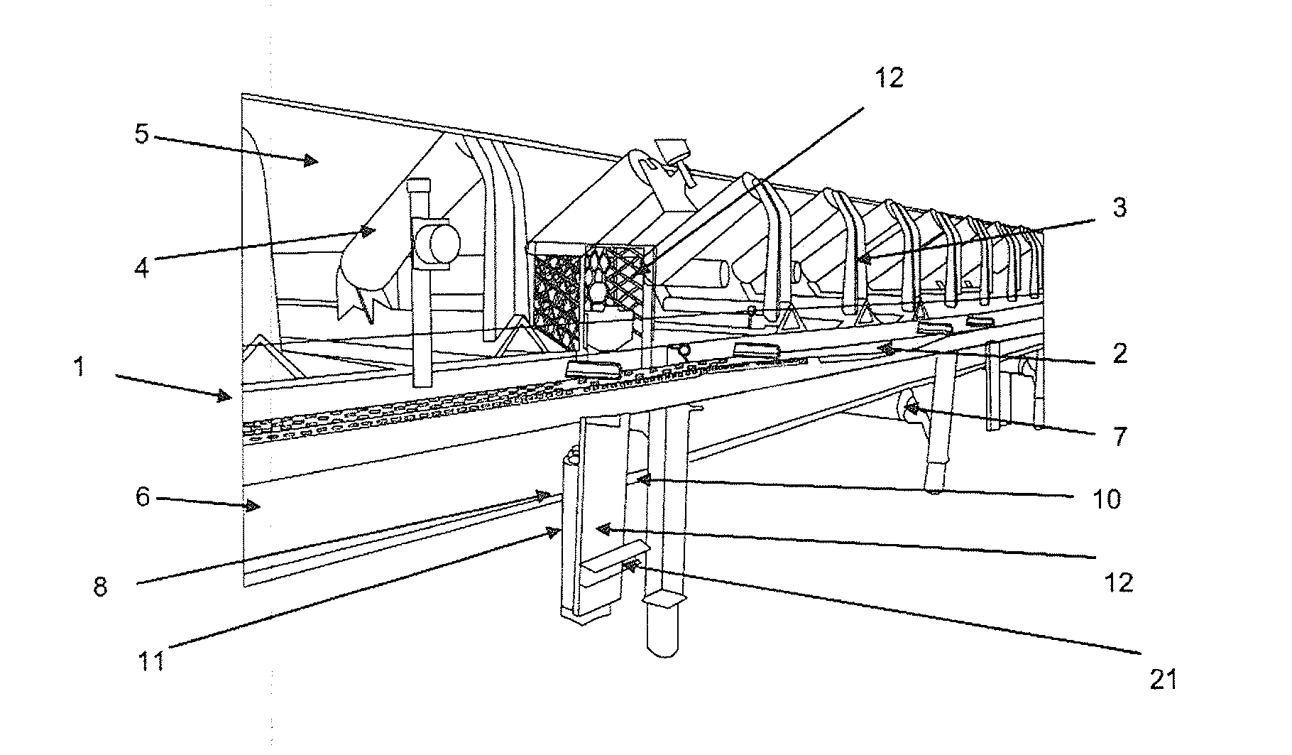
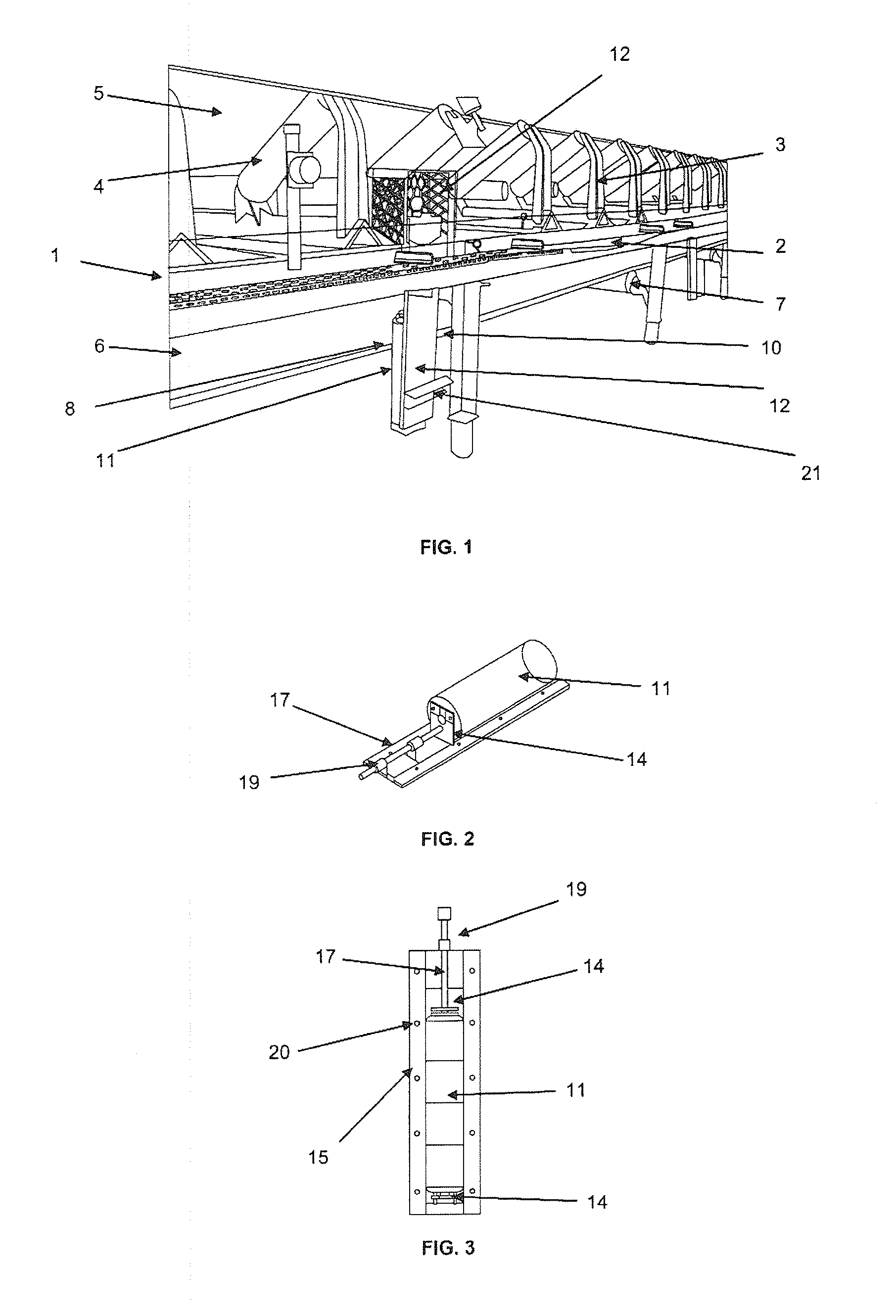
[0035]FIG. 1 shows a part of a conveyor belt 1 having a support structure 2 whereon there are mounted the easels that support a plurality of load rollers 4.

[0036]The load rollers 4 support the portion of the conveyor belt 5 that moves in the direction of the transport of the material. The load rollers are resistant enough to support not only the belt but also the weight of the material transported thereon.

[0037]The return portion of the belt 6 moves in the direction opposite that of the transport. Return rollers 7 are provided to support the return portion of the belt 6.

[0038]The return rollers 7 are generally more spaced than the load rollers 4, such that the presence of guide rollers is necessary to prevent diversion or misalignment of the belt 6. The guide rollers rotate on their own axis, so as to accompany the movement of the belt.

[0039]The present in...


PUM


Abstract

The present invention refers to a belt guide device for use in conveyor belts and, more specifically, to a guide roller device that decreases the need to replace the rollers and prevents the formation of rubber strips by contact between the belt of the conveyor and the roller. Thus, the device of the present invention comprises: the guide roller, a sliding board whereon the guide roller is mounted, a support track that receives the sliding board, and an adjustment mechanism connected to the sliding board to trigger, selectively, the sliding thereof in relation to the support track. The support track is fastened to the structure in a position such that the guide roller is situated closely adjacent to the edge of the belt.

Description

FIELD OF THE INVENTION[0001]The present invention refers to a belt guide device for use in conveyor belts and, more specifically, to a guide roller device that decreases the need to replace guide rollers and prevents the formation of rubber strips by contact between the belt and the roller.BACKGROUND OF THE INVENTION[0002]Conveyor belts solutions are broadly known in the art for the transport of articles from one place to another. Said solutions basically comprise a conveyor / belt made of rubber or other suitable material which moves propelled by rollers or other drive devices. A support, generally in the shape of a table, trough or easel, supports the drive rollers and other structures required for the working of the conveyor belt (load rollers, return rollers, curve devices, smaller easels, etc.).[0003]In order to guarantee the belt path and to prevent misalignment during its movement, guide rollers may be provided adjacent to the belt edges. Said guide rollers are generally dispos...

Claims


Application Information

Patent Timeline
Patent Type & Authority Applications(United States)
IPC IPC(8): B65G15/60
CPCB65G15/60B65G39/16
Inventor CRUZ, ANTONIO MARCOS TORRESHORTENCIO, BRUNO FREITASSANTANA, GLAUSCOCORREA, JR., JOSE DA PAZRISSI, PATRICK FARIASDE AZEVEDO, SERGIO GONCALVESDA SILVA, ULISSES CHAVES
Owner VALE LIMITED
Why Eureka
Try Eureka