Supercharge Your Innovation With Domain-Expert AI Agents!

Transformation of Bi-Directional Packet Flow

a packet flow and transformation technology, applied in the field of packet flow, can solve the problems of inability to identify optimally functional packet flows, inability to classify incoming packets, and limit packet processing in network processors

Inactive Publication Date: 2014-01-30
INT BUSINESS MASCH CORP
View PDF0 Cites 0 Cited by
  • Summary
  • Abstract
  • Description
  • Claims
  • Application Information

AI Technical Summary

Benefits of technology

This solution facilitates the identification of bidirectional packet flows with a single flow identifier, improving hardware efficiency by minimizing silicon area requirements and enabling effective packet processing on high-speed interfaces, allowing packets from both sides of a connection to be managed and processed uniformly.

Problems solved by technology

A traditional limitation related to packet processing in network processors is packet flow bi-directionality.
In general, existing network processors do not allow optimal identification of functional packet flows for packets exchanged in either direction on a connection.
Existing solutions do not allow a classification of incoming packets by network connection independent of which port has received the packet, i.e., a same classification usually cannot be performed for packets related to the two sides of a same network connection.
Accordingly, packets of both sides of the network connection cannot be easily managed to be received in a same receive queue and / or sent for final processing to a same processing core or thread.

Method used


Image

  • Transformation of Bi-Directional Packet Flow
  • Transformation of Bi-Directional Packet Flow
  • Transformation of Bi-Directional Packet Flow

Examples


Embodiment Construction

[0017]As will be appreciated by one of ordinary skill in the art, the present invention may be embodied as a method, system, device, or computer program product. Accordingly, the present invention may take the form of an embodiment including hardware, an embodiment including software (including firmware, resident software, microcode, etc.) or an embodiment combining software and hardware aspects that may all generally be referred to herein as a circuit, module, or system. The present invention may, for example, take the form of a computer program product on a computer-usable storage medium having computer-usable program code, e.g., in the form of one or more design files, embodied in the medium.

[0018]Any suitable computer-usable or computer-readable storage medium may be utilized. The computer-usable or computer-readable storage medium may be, for example, but is not limited to, an electronic, magnetic, optical, electromagnetic, infrared, or semiconductor system, apparatus, or devic...


PUM


Abstract

A network packet includes a packet key that includes one or more source-destination field pairs. Each source-destination field pair that is included in the one or more source-destination field pairs includes a source field and a destination field. For each selected source-destination field pair, included in the one or more source-destination field pairs, a first section and a second section are selected in the packet key. A source field value is extracted from the source field and a destination field value is extracted from the destination field of the selected source-destination field pair.

Description

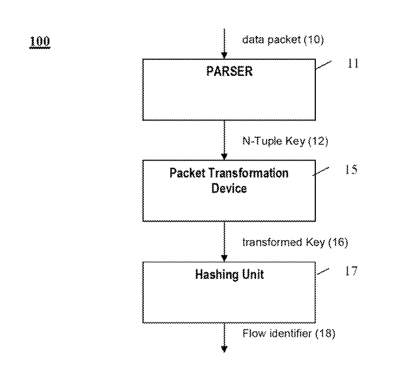
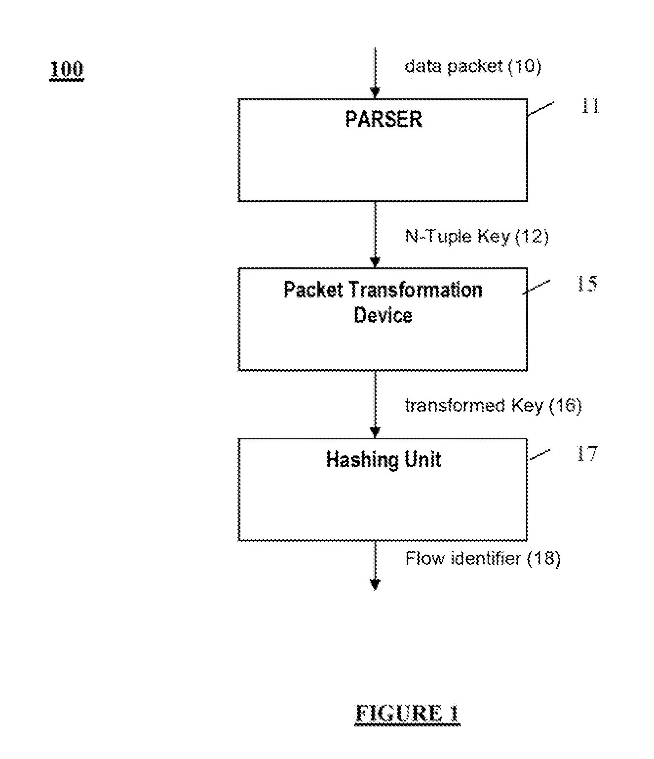
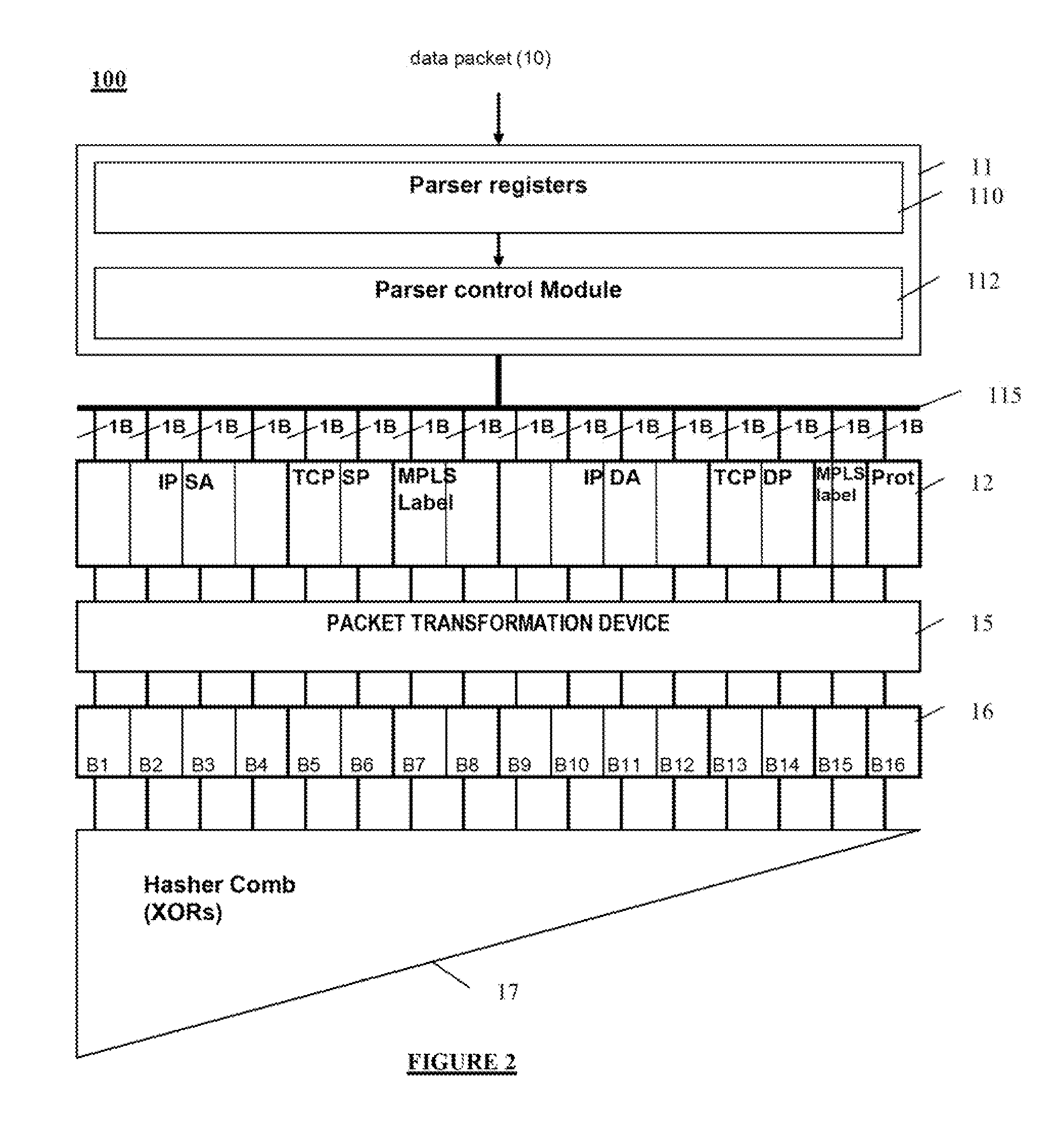
[0001]This application is a continuation of U.S. patent application Ser. No. 13 / 325,624, entitled “Bidirectional Packet Flow Transformation,” filed on Dec. 14, 2011, which claims priority to European Patent Application No. EP10306403, entitled “Bidirectional Packet Flow Transformation,” filed Dec. 14, 2010, the disclosures of which are hereby incorporated herein by reference in their entirety for all purposes.BACKGROUND[0002]1. Field[0003]This disclosure relates generally to packet flow and, more specifically, to bidirectional packet flow transformation.[0004]2. Related Art[0005]As network processors become more pervasive, technology is constantly developing to provide more flexibility and improved capabilities with respect to network packet processing features. Network processors process and route packets formatted according to a given protocol (e.g., transmission control protocol (TCP)), based on computations performed on packet fields. A traditional limitation related to packet p...

Claims


Application Information

Patent Timeline
Patent Type & Authority Applications(United States)
IPC IPC(8): H04L29/06H04L45/50
CPCH04L29/0653H04L45/50H04L47/2441H04L69/22
Inventor BASSO, CLAUDECALVIGNAC, JEAN L.VAIDHYANATHAN, NATARAJANVERPLANKEN, FABRICE
Owner INT BUSINESS MASCH CORP
Features
  • R&D
  • Intellectual Property
  • Life Sciences
  • Materials
  • Tech Scout
  • Unparalleled Data Quality
  • Higher Quality Content
  • 60% Fewer Hallucinations
Learn More