Knife holder having a blade changing apparatus

Active Publication Date: 2014-02-06
LEICA BIOSYST NUSSLOCH
View PDF3 Cites 9 Cited by
  • Summary
  • Abstract
  • Description
  • Claims
  • Application Information

AI Technical Summary

Benefits of technology

[0005]The present invention proposes a knife holder for a microtome, wherein the knife holder has a blade changing apparatus.
[0006]In a knife holder according to the present invention, a used blade no longer needs to be pushed out of the blade receptacle of the cutting position (hereinafter the “first blade receptacle”) by a new blade. Instead, it can be delivered by means of gravity, e.g. can fall or slide or slip out, into a blade receptacle of a disposal position (hereinafter the “second blade receptacle”). A new blade can then be slid into the unoccupied blade receptacle of the cutting position so that no risk of jamming or oversliding exists. The particular configuration also makes it possible for the used blade to be disposed of to the side on which the new blades are also located, so that the width of the knife holder can be reduced. Instead of three blade lengths as in the existing art, only two blade lengths are now needed.
[0007]A securing means, e.g. a clamping mechanism, for securing a blade in the first blade receptacle, and an ejection means, e.g. a movable lug, for ejecting a blade received in the first blade receptacle out of the first blade receptacle, are usefully connected to the same actuation means, e.g. to a lever, in order to be actuated thereby.
[0008]In a preferred embodiment, the first blade receptacle and the second blade receptacle are arranged vertically spaced apart in the knife holder. This is a particularly simple construction for utilizing gravity, without which, for example, a r

Problems solved by technology

This design requires a relatively large amount of space.
The sliding out of

Method used


Image

  • Knife holder having a blade changing apparatus
  • Knife holder having a blade changing apparatus
  • Knife holder having a blade changing apparatus

Examples


Embodiment Construction

[0021]The Figures are described below together and continuously, identical elements being labeled with identical reference characters.

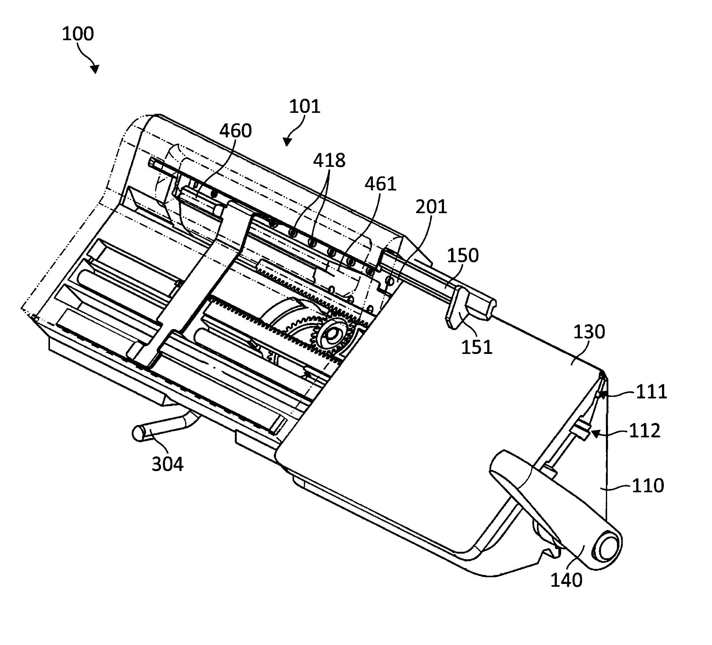
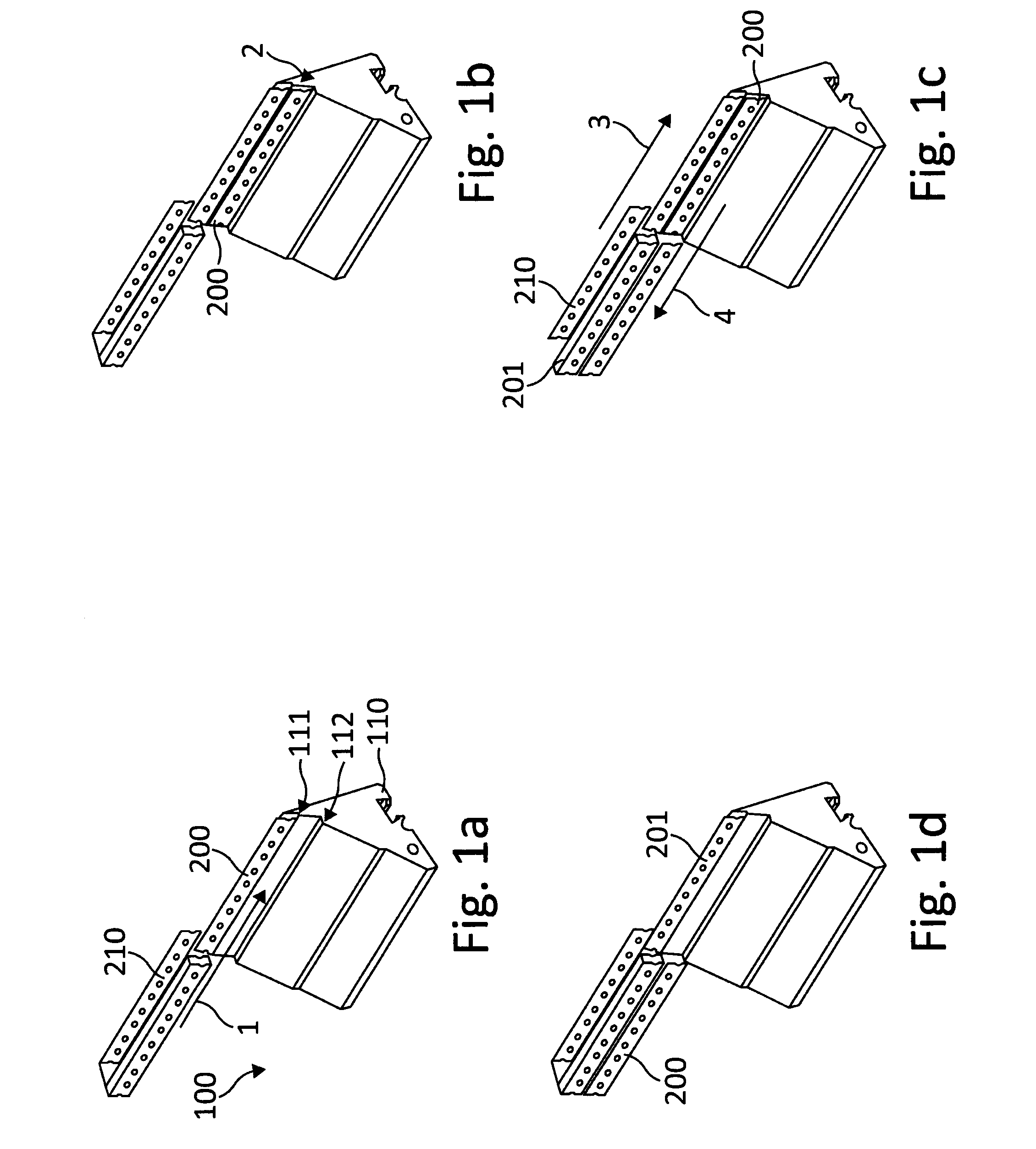
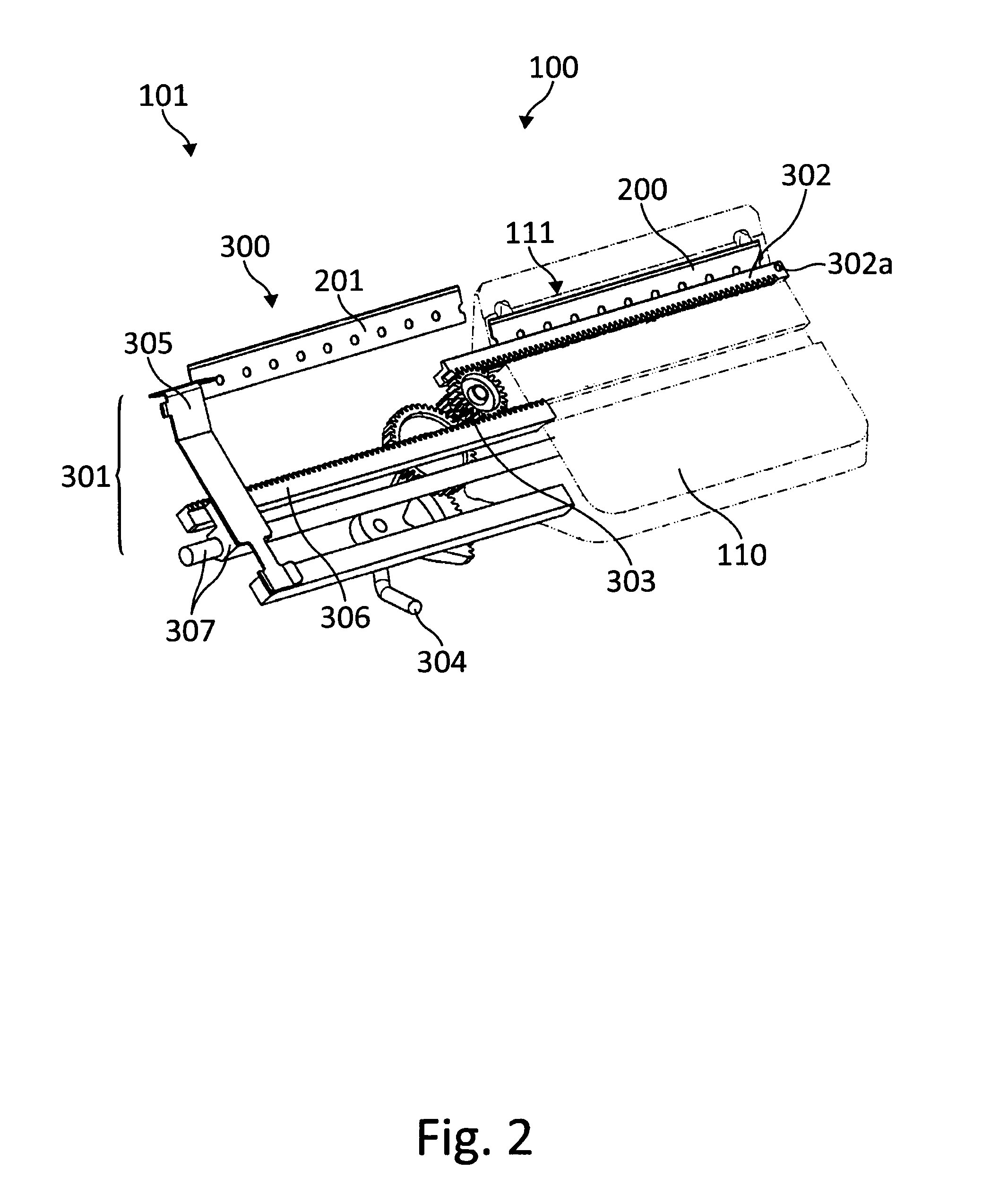
[0022]FIGS. 1a to 1d show various steps or states of a blade changing operation with reference to a schematic depiction of a few elements of a knife holder 100. The sequence of FIGS. 1a to 1d corresponds to the sequence in time. FIG. 2 shows knife holder 100, with elements of a blade changing apparatus 101, in a state according to FIG. 1c.

[0023]FIG. 3 is a schematic, perspective view of knife holder 100 with further elements for better clarity, and FIGS. 4 and 6 each show a cross-sectional view through knife holder 100.

[0024]A knife block 110 of a knife holder 100 is depicted, comprising in its upper region two steps 111 and 112 that each form a blade receptacle. Step 111 forms a first blade receptacle for a cutting position, and step 112 forms a second blade receptacle for a disposal position. A blade that is located in first blade receptacle 111 is...


PUM

PropertyMeasurementUnit
Gravityaaaaaaaaaa

Abstract

The invention relates to a knife holder (100) having a blade changing apparatus (102). The knife holder has a first blade receptacle (111) defining a cutting position, a securing means (130, 141, 142) for securing a blade (201) received in the first blade receptacle (111), a second blade receptacle (112) defining an output position, and an ejection means (141, 143, 144a) for ejecting a blade (201) received in the first blade receptacle (111) out of the first blade receptacle (111). The first and the second blade receptacles are arranged in the knife holder in such a way that a blade ejected from the first blade receptacle (111) can travel by gravity into the second blade receptacle (112).

Description

CROSS REFERENCE TO RELATED APPLICATIONS[0001]This application claims priority of German patent application number 10 2012 213 824.2 filed Aug. 3, 2012, the entire disclosure of which is incorporated by reference herein.FIELD OF THE INVENTION[0002]The present invention relates to a knife holder having a blade changing apparatus for a microtome.BACKGROUND OF THE INVENTION[0003]Microtomes are used, for example, to prepare thin sections of tissue that can then be investigated microscopically. Microtomes have for this purpose a knife holder having a very sharp blade. Disposable blades have become established in particular in the laboratory sector, a blade being disposed of after a number of sectioning operations and replaced with a new blade. One such knife holder is described in DE 10 2004 051 974 A1. Here the blades must be changed manually. As an improvement, DE 10 2007 006 826 B1 describes a knife holder in which blade changing is assisted by a driver. New blades are taken out of a b...

Claims


Application Information

Patent Timeline
IPC IPC(8): G01N1/06
CPCG01N1/06G01N2001/061Y10S83/9155Y10S83/954Y10T83/6492Y10T83/6499Y10T83/9457Y10T483/17B26D7/2614B23Q3/155
Inventor WALTER, ROLAND
Owner LEICA BIOSYST NUSSLOCH
Why Eureka
Try Eureka