
Wheel for pedal-assisted bikes

a pedal-assisted bike and wheel technology, applied in the direction of wheels, wheel-axle combinations, vehicle transmission, etc., can solve the problems of inconvenient and not very practical operations, motorised wheels for pedal-assisted bikes cannot always be combined in a practical and easy way, combined with gear change devices insid

Active Publication Date: 2014-02-06
C R D CENT RICERCHE DUCATI TRENTO
View PDF3 Cites 28 Cited by
  • Summary
  • Abstract
  • Description
  • Claims
  • Application Information

AI Technical Summary

Benefits of technology

The invention is about a new wheel for pedal-assisted bicycles that can be easily fitted onto any existing bike model. The wheel offers the same functions and benefits of a traditional pedal-assisted bike, but in a simple and cost-effective way. The technical effect of the invention is to provide a practical solution for transforming any bike into a powerful and easy-to-use electric bike.

Problems solved by technology

Only rarely in fact is it possible to develop a kit able to adapt to several bike models, taking into account the considerable differences between the bicycles on the market, in particular their frames which, of course, have shapes and dimensions so different as to prevent a practical and complete standardisation of pedal-assisted systems.
It must also be underlined that the fitting of a kit for pedal-assisted bikes during the after-sales stage, even if this were possible, usually calls for the performance of inconvenient and not very practical operations concerning the adjustment and the fitting of the various components to the frame which more often than not cannot be performed by the end user and requires the intervention of an expert technician.
To this must be added that, quite apart from where the battery pack is positioned either on the wheel or on the frame, the motorised wheels for pedal-assisted bikes can not always be combined in a practical and easy way with the traditional mechanical gears usually used to reduce or multiply the motion transmission ratio from the pedal crank.
The fact that the hub of the motorised wheel is almost completely occupied by the electric motor in fact determines the fact that this wheel cannot be combined with gear change devices inside the hub, such as, e.g., the Rohloff gear change but can only be combined with external devices, such as traditional derailleur gears, which nevertheless are not standardised and vary according to the bike model.

Method used


Image

  • Wheel for pedal-assisted bikes
  • Wheel for pedal-assisted bikes
  • Wheel for pedal-assisted bikes

Examples


Embodiment Construction

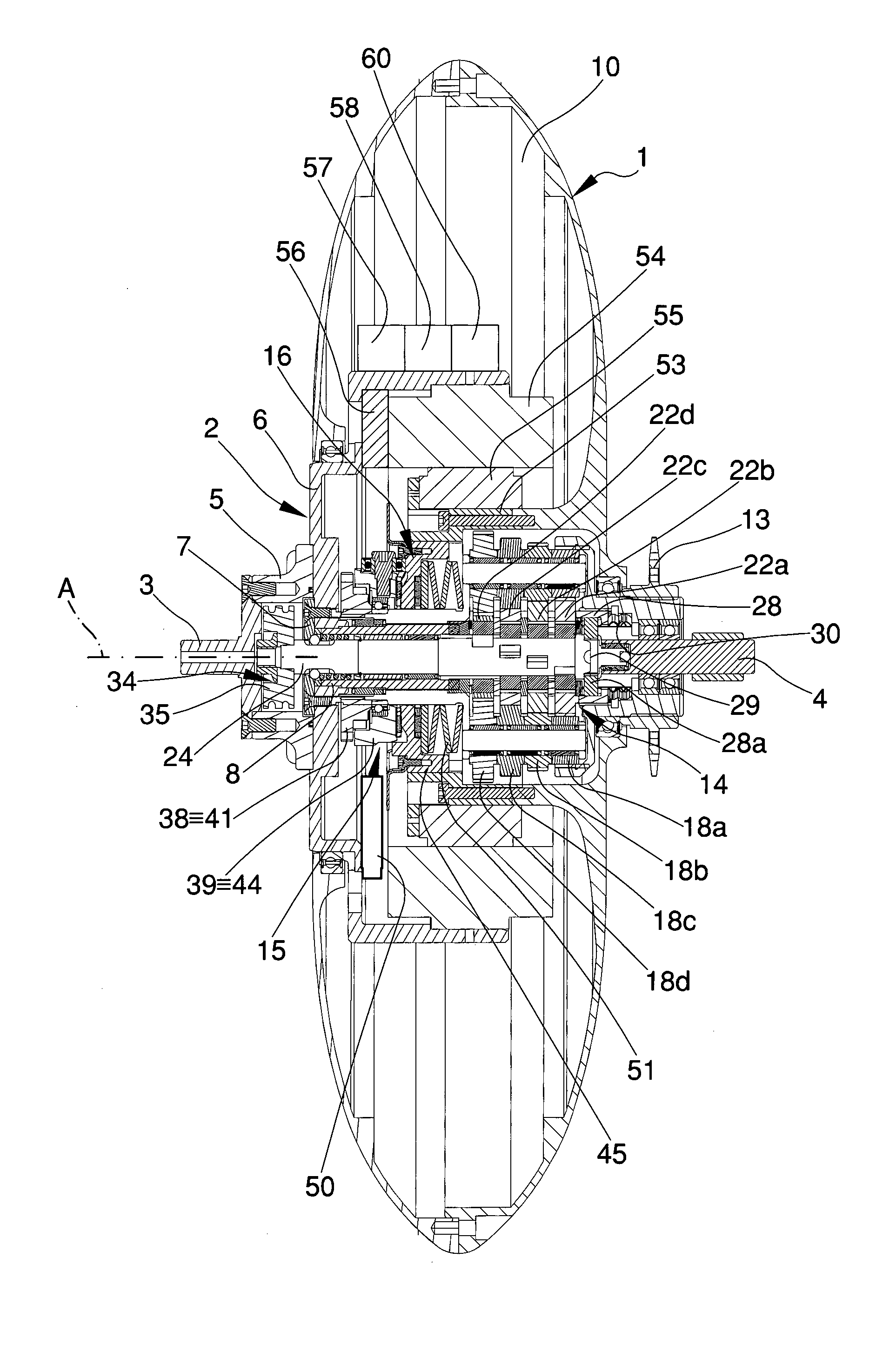
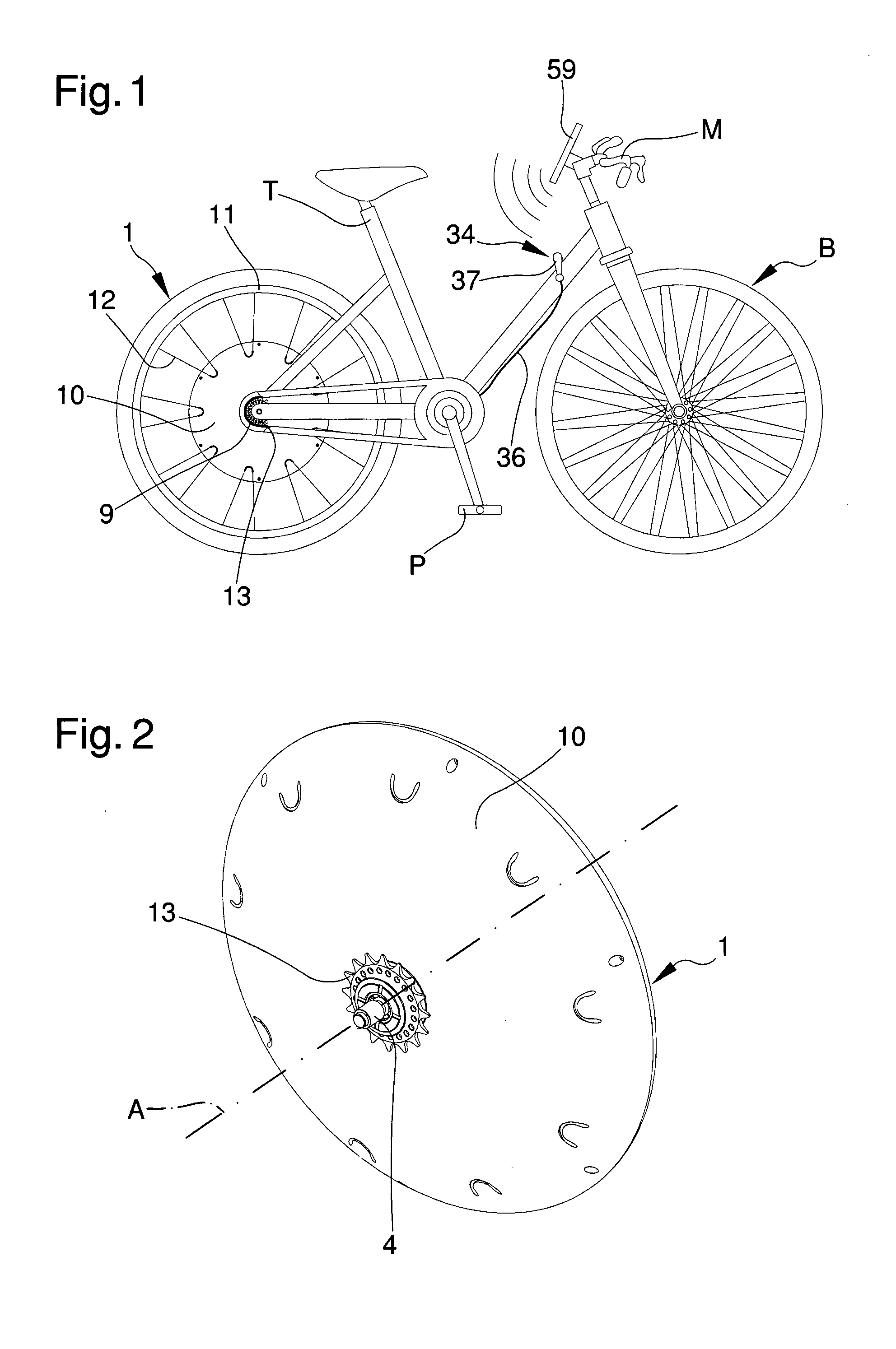
[0017]The main object of the present invention is to provide a wheel for pedal-assisted bike that can be fitted on any traditional already-existing bike model, providing this, in a practical, easy and functional way, with the functions of pedal-assisted bikes.

[0018]Another object of the present invention is to provide a wheel for pedal-assisted bikes that allows overcoming the mentioned drawbacks of the background art within the ambit of a simple, rational, easy and effective to use as well as low cost solution.

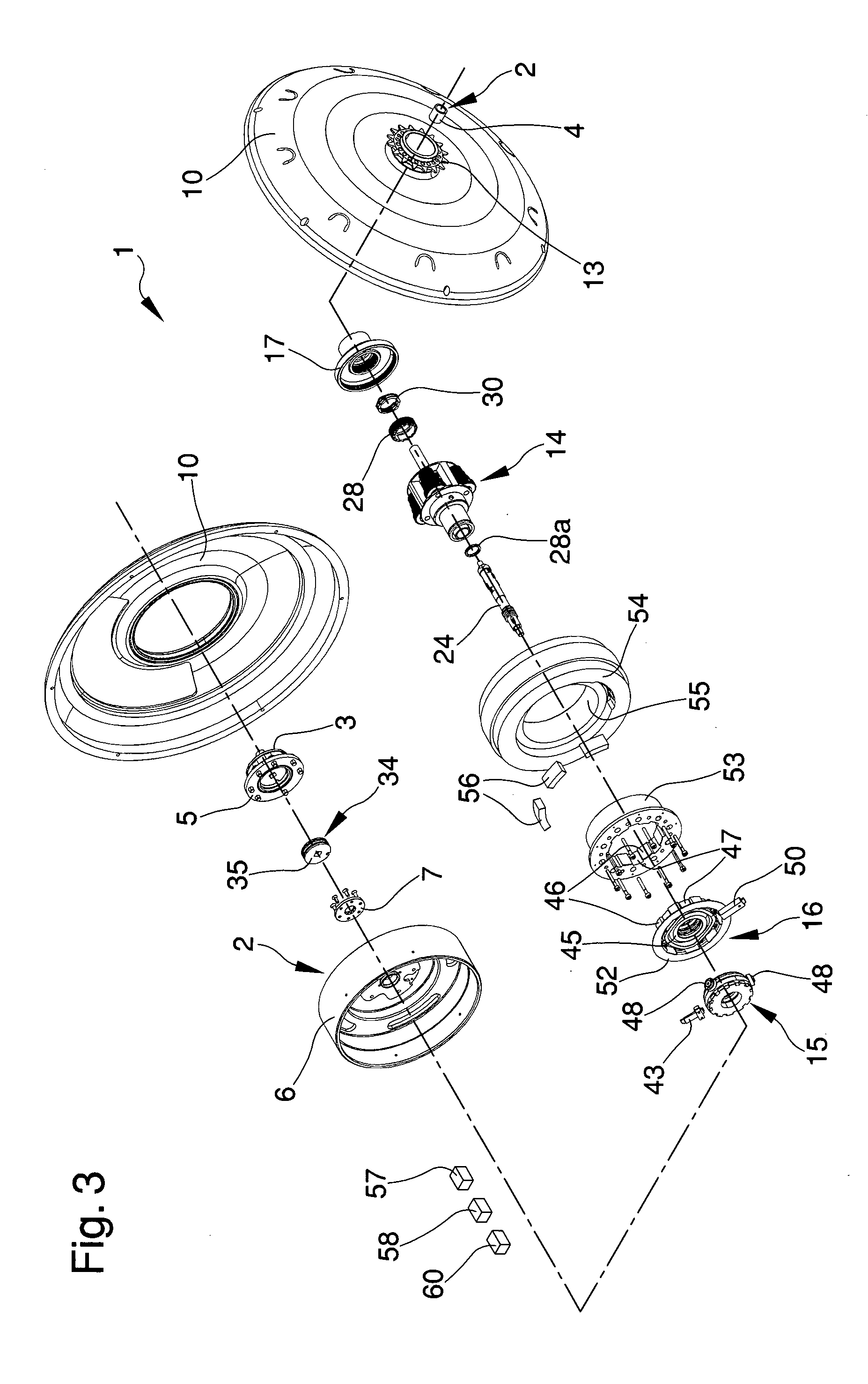
[0019]The above mentioned objects are achieved by the present wheel for pedal-assisted bikes, characterised in that it comprises:[0020]at least a fixed structure associable with the frame of a bike having a driving pedal crank;

[0021]at least a circle element mounted on said fixed structure in a rotatable way around a main rotation axis;[0022]at least a propulsion disc mounted on said fixed structure in a rotatable way and connectable to said driving pedal crank;[0023]motion t...


PUM


Abstract

A wheel for pedal-assisted bikes includes:a fixed structure associable with the frame of a bike having a driving pedal crank;a circle element mounted on the structure in a rotatable way around a main rotation axis;a propulsion disc rotatably mounted on the structure and connectable to the driving pedal crank;motion transmission elements for transmitting rotary motion from the disc to the circle element, including:a speed gear device for changing the motion transmission ratio from the disc to the circle element; anda first detection device suitable for detecting the force transmitted to the circle element from the disc;an electric motor associated with the structure for cooperating with the disc to motorize the circle element;a power supply for electrically supplying the motor;a processing and control unit for controlling the activation of the motor according to the force detected by the first detection device.

Description

TECHNICAL FIELD[0001]The present invention relates to a wheel for pedal-assisted bikes.BACKGROUND ART[0002]Pedal-assisted bikes are bicycles with an auxiliary electric motor having the following specifications:[0003]maximum continuous power rating of the electric motor: 0.25 kW;[0004]motor supply gradually reduced and interrupted when 25 km / h is achieved;[0005]motor supply interrupted before 25 km / h if the cyclist stops pedalling.[0006]The electric motor is controlled by means of a processing and control unit which controls the power supply according to the pedal force of the user, balancing the engagement of the transmission gradually from when pedalling starts, to make this smooth and regular.[0007]For this purpose, pedal-assisted bikes have a force sensor in correspondence to the pedals or a speed sensor positioned in the pedal crank or both.[0008]In traditional pedal-assisted bikes, the electric motor is housed directly in the hub of the motorised wheel and is powered by a batte...

Claims


Application Information

Patent Timeline
IPC IPC(8): B62M6/65
CPCB62M6/65B62M6/50B62M11/16
Inventor ZANFEI, ADRIANOGIORGI, FABIO
Owner C R D CENT RICERCHE DUCATI TRENTO
Learn More