High-frequency front-end circuit

Active Publication Date: 2014-02-06
MURATA MFG CO LTD
View PDF2 Cites 38 Cited by
  • Summary
  • Abstract
  • Description
  • Claims
  • Application Information

AI Technical Summary

Benefits of technology

[0027]According to various preferred embodiments of the present invention, despite using a simple circuit configuration, transmission and reception of a plurality of communicatio

Problems solved by technology

Consequently, the scale of the circuit may be increased and it may be difficult to reduce the cost.
In addition, since the transmission frequency band and the reception frequency band overlap for a TDD-scheme communication signal, in the high-frequency front-end ci

Method used


Image

  • High-frequency front-end circuit
  • High-frequency front-end circuit
  • High-frequency front-end circuit

Examples


Embodiment Construction

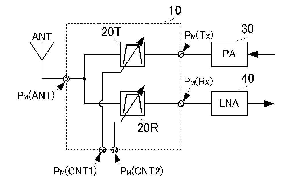
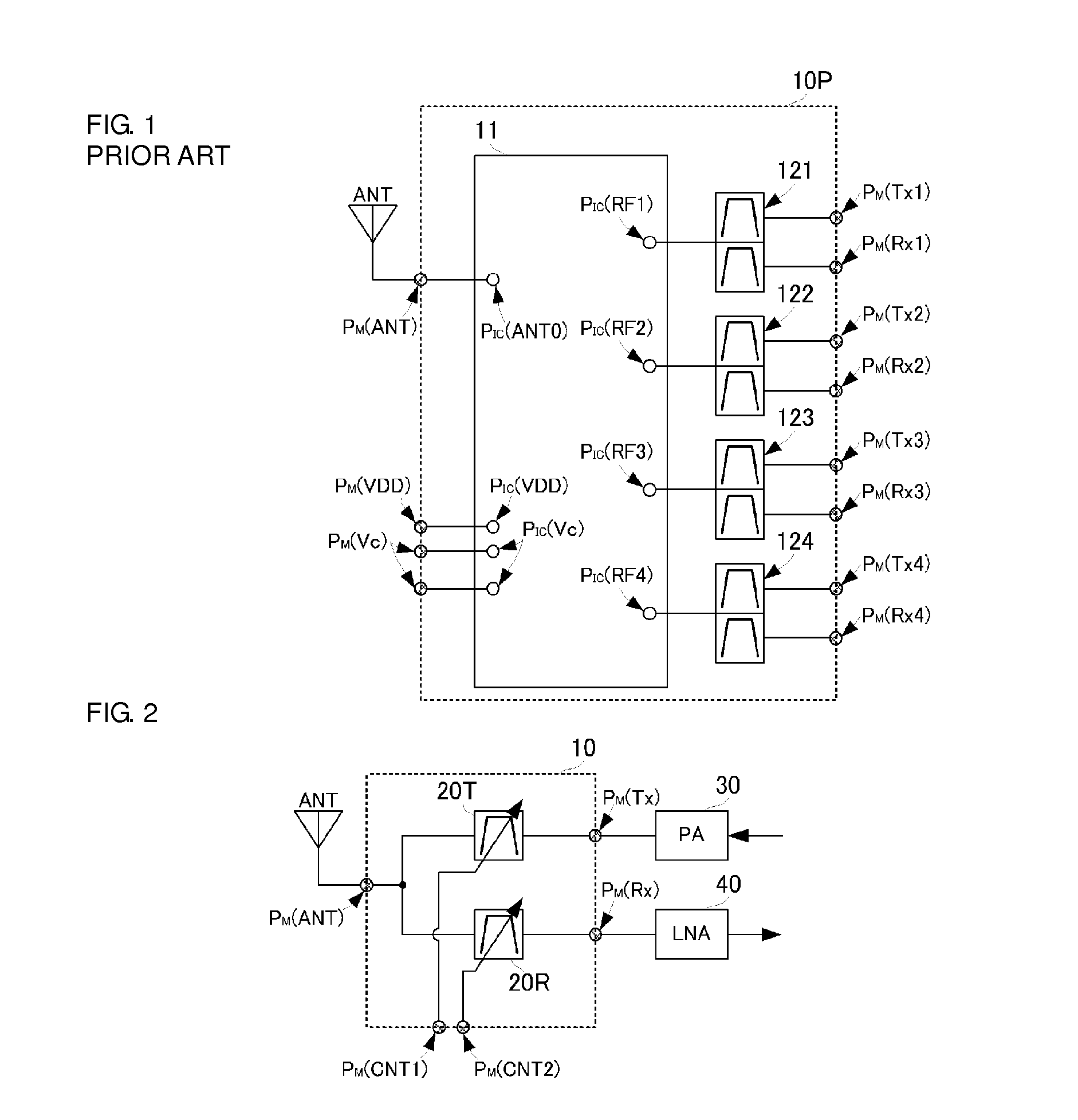
[0034]A high-frequency front-end circuit according to a first preferred embodiment of the present invention will be described with reference to the drawings. FIG. 1 is a circuit configuration diagram of a high-frequency front-end circuit 10 according to this preferred embodiment.

[0035]The high-frequency front-end circuit 10 includes variable filters 20T and 20R. The variable filter 20T corresponds to a first variable filter and the variable filter 20R corresponds to a second variable filter. In this preferred embodiment, a case is illustrated in which the variable filter 20T serves as a transmission filter and the variable filter 20R serves as a reception filter for specific communication signals (transmission signal and reception signal). Therefore, a variable duplexer includes the variable filter 20T and the variable filter 20R.

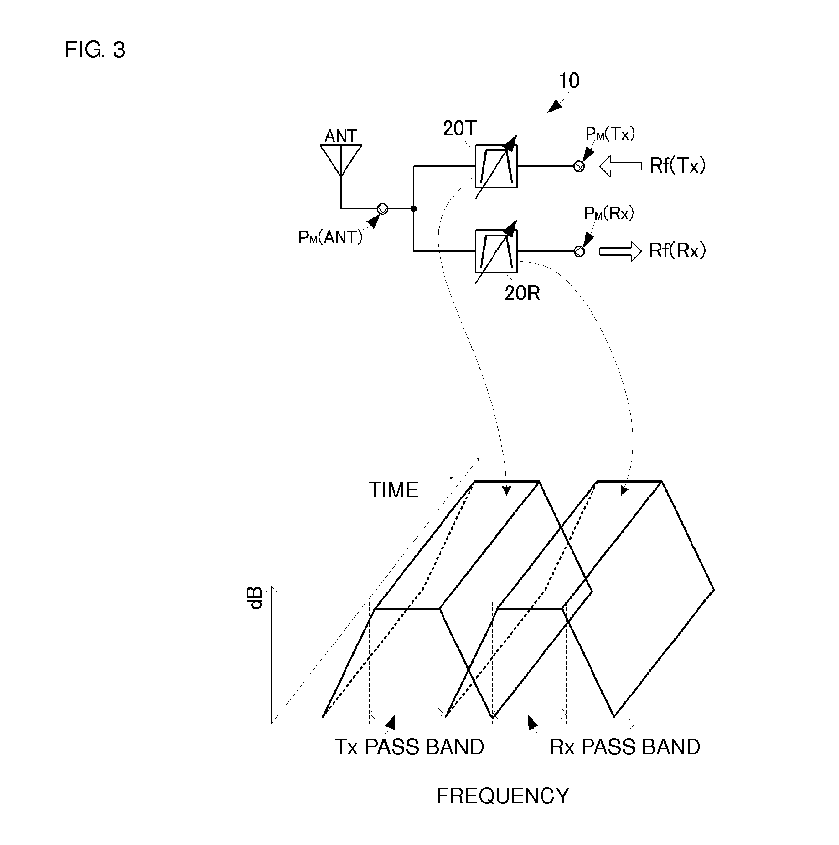
[0036]The variable filters 20T and 20R are each configured such that the pass frequency band and the attenuated frequency band thereof are adjustable. In a...


PUM


Abstract

A high-frequency front-end circuit includes a first variable filter and a second variable filter. One end of each of the variable filters is connected to a common terminal. The other end of the first variable filter is connected to a transmission individual terminal and the other end of the second variable filter is connected to a reception individual terminal. At the time of transmission of a transmission signal, the impedance of the second variable filter is adjusted such that the impedance seen on the second variable filter side from a connection point between the variable filters is open. At the time of transmission of a reception signal, the impedance of the first variable filter is adjusted such that the impedance seen on the first variable filter side from a connection point between the variable filters is open.

Description

BACKGROUND OF THE INVENTION[0001]1. Field of the Invention[0002]The present invention relates to high-frequency front-end circuits that transmit and receive a plurality of communication signals having different communication schemes.[0003]2. Description of the Related Art[0004]To date, various high-frequency front-end circuits for transmitting and receiving a plurality of communication signals utilizing different frequency bands with a common antenna have been devised. FIG. 1 is a circuit configuration diagram of a typical high-frequency front-end circuit 10P of the related art. The high-frequency front-end circuit illustrated in FIG. 1 illustrates an example in which four different types of communication signals are transmitted and received using a common antenna.[0005]The high-frequency front-end circuit 10P of the related art includes a switch device 11 and SAW duplexers 121, 122, 123 and 124. The switch device 11 has a common terminal PIC (ANT0) and individual terminals PIC (RF1...

Claims


Application Information

Patent Timeline
IPC IPC(8): H04B1/40
CPCH04B1/40H04B1/0057
Inventor HAYAFUJI, HISAOMIZOGUCHI, SHINYAOBIYA, HIDENORI
Owner MURATA MFG CO LTD
Why Eureka
Try Eureka