Method of detecting defects of a rolling bearing by vibration analysis

a vibration analysis and bearing technology, applied in the direction of mechanical measurement arrangements, mechanical roughness/irregularity measurements, instruments, etc., can solve the problems of wear, deterioration of the operation of the bearing, and swarf coming,

Active Publication Date: 2014-02-06
EUROCOPTER
View PDF5 Cites 32 Cited by
  • Summary
  • Abstract
  • Description
  • Claims
  • Application Information

AI Technical Summary

Benefits of technology

[0024]An object of the present invention is to propose a method that makes it possible to mitigate the above-mentioned drawbacks so as to detect defects in elements of a rolling bearing in a manner that is reliable, early, and fast, by analyzing a vibration signal.

Problems solved by technology

By way of example, this wear may be in the form of degradation in the surface roughness of the inner and outer rings and also in the surface roughness or even in the shape of the rolling bodies.
Such wear may also give rise to the appearance of swarf coming from the rolling bodies or from the rings.
Such wear can then generate impacts during the operation of the bearing and these lead to degradation in its operation, and consequently to degradation in the transmission of rotary motion and torque.
By way of example, this degradation may go so far as to cause the bearing to seize and jam completely, thereby making it impossible to transmit the rotary motion and torque.
Such impacts may also give rise to cracking in at least one of the rings and may lead to the ring breaking and thus to the bearing being destroyed.
The drawbacks that can be found in those various methods lie mainly in the difficulty of isolating the frequencies that relate to defects in the elements of the bearing, and also to the level of reliability that can be given to those frequencies.
The measured signal does indeed contain the frequencies of the vibrations emitted by the bearing and by its elements, but it also contains interfering vibrations that pollute the measured signal and that prevent the vibration frequencies that reveal the looked-for defects from being isolated effectively.
Those interfering vibrations are emitted mainly by other components in the proximity of the bearing, such as the shaft and the components of the guide device.
Those interfering vibrations may be generated firstly by the rotation of the shaft and the torque it is transmitting and also by the stresses to which it is subjected, and secondly by external elements, such as the explosions in an engine to which the shaft is connected or the vibration of a vehicle in which the guide device is installed.
The difficulty that is encountered for isolating the frequencies of the defects of bearing elements makes it difficult to estimate a reliability level for such defect detection.
In contrast, certain methods require successive measurements in order to detect variation in the behavior of elements of a bearing that might correspond to a degradation of such an element, and as a result they are not suitable for such systems.

Method used


Image

  • Method of detecting defects of a rolling bearing by vibration analysis
  • Method of detecting defects of a rolling bearing by vibration analysis
  • Method of detecting defects of a rolling bearing by vibration analysis

Examples


Embodiment Construction

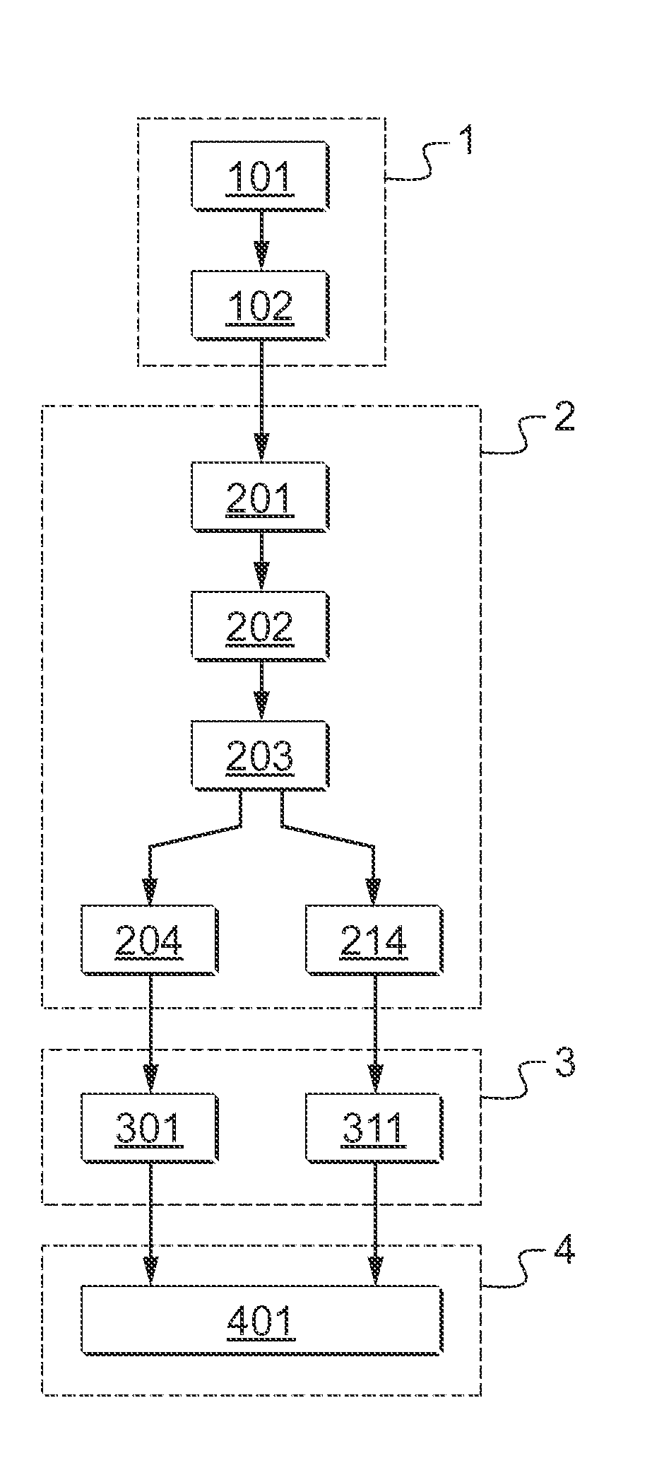
[0094]FIG. 1 is a diagram summarizing the method of the invention that takes place in four main steps, each of these main steps comprising one or more substeps. The method is a method of detecting defects in a rolling bearing 10 by analyzing vibration.

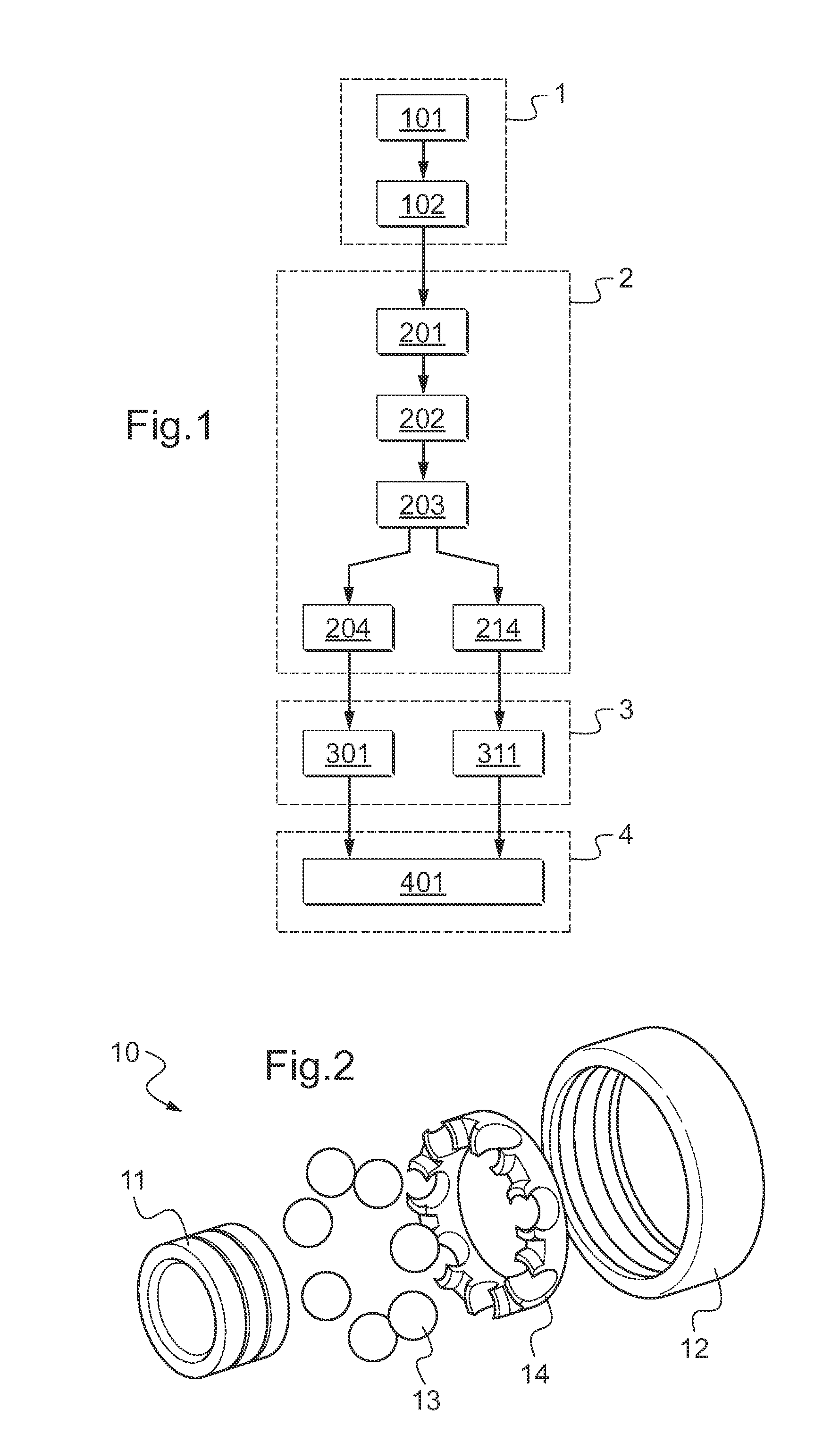
[0095]An exploded view of one such bearing 10 is shown in FIG. 2. The bearing 10 comprises several components, including an inner ring 11, an outer ring 12, and a plurality of balls 13. It may also have a cage 14 serving to keep the spacing between the balls 13 constant. The balls 13 can roll between the inner and outer rings 11 and 12. Nevertheless, the balls 13 may be replaced by any other type of rolling body, e.g. by cylindrical or conical rollers, or indeed by barrel-shaped rollers.

[0096]The bearing 10 is generally part of a device for guiding a component in rotation, such as a shaft transmitting rotary motion and torque. The guide device is itself incorporated in a system, such as an engine.

[0097]Firstly, during a preliminary ste...


PUM

PropertyMeasurementUnit
timeaaaaaaaaaa
frequency αthaaaaaaaaaa
frequency dispersion Δfaaaaaaaaaa

Abstract

A method of detecting defects in a rolling bearing (10). The method includes acquiring a time-domain vibration signal An; filtering said time-domain vibration signal An; and then resolving it to obtain a deterministic time-domain vibration signal Fn and a random time-domain vibration signal Gn. Thereafter, the time-domain vibration signals Fn and Gn are transformed respectively into a deterministic frequency-domain vibration signal Jn and into a random frequency-domain vibration signal Kn, and then, for each element (11, 12, 13) and for each frequency-domain vibration signal Jn, Kn, a defect-presence frequency {circumflex over (α)} is determined corresponding to a maximum probability of the presence of a defect in said element (11, 12, 13) and to an associated reliability level p({circumflex over (α)}). An alert message indicating at least one defect in at least one element (11, 12, 13) is potentially delivered depending on the values of each defect-presence frequency {circumflex over (α)} and on each associated reliability level p({circumflex over (α)}).

Description

CROSS REFERENCE TO RELATED APPLICATIONS[0001]This application claims priority to French patent application No. FR 12 02152 filed on Jul. 31, 2012, the disclosure of which is incorporated in its entirety by reference herein.BACKGROUND OF THE INVENTION[0002](1) Field of the Invention[0003]The present invention lies in the field of methods of monitoring a rolling bearing serving to provide at least some of the rotary guidance of at least one component. The invention relates more particularly to a method of detecting defects of a bearing by vibration analysis.[0004](2) Description of Related Art[0005]A bearing generally acts in co-operation with at least one other bearing to provide rotary guidance for a component such as a shaft in a housing that is generally stationary, e.g. for the purpose of transmitting rotary motion and torque. Nevertheless, it is possible for the shaft to be stationary and the housing to rotate about the shaft in order to transmit rotary motion and torque. It is ...

Claims


Application Information

Patent Timeline
Patent Type & Authority Applications(United States)
IPC IPC(8): G01N29/44
CPCG01N29/4463G01H1/00G01M13/045
Inventor GIRONDIN, VICTORCASSAR, JEAN-PHILIPPE
Owner EUROCOPTER
Why Eureka
Try Eureka