
Area monitoring system and corresponding method for operating the same

Active Publication Date: 2014-02-06
TELECOM ITALIA SPA
View PDF0 Cites 25 Cited by
  • Summary
  • Abstract
  • Description
  • Claims
  • Application Information

AI Technical Summary

Benefits of technology

The patent text discusses the problem of monitoring environments with high precision using affordable sensor units. However, there are environmental conditions that require more expensive and power-hungry sensor units, which results in high installation and management costs. The proposed monitoring system aims to improve energy efficiency, reduce installation and management costs, and provide a reliable service capable of monitoring the area with high accuracy. It uses a combination of static sensor units and mobile robots managed by a central unit, making it more flexible and efficient compared to known monitoring systems. This also reduces the number of robots needed, resulting in lower costs. The central unit drives the robots towards the areas where monitoring is most required.

Problems solved by technology

The Applicant has found that the abovementioned systems known in the art implementing an area monitoring service are affected by several drawbacks.
Specifically, even if a monitoring system arranged as a sensor network may be advantageously implemented with relatively inexpensive sensor units, if the environmental condition(s) object of the monitoring system requires to be monitored with high precision, more sophisticated (and more expensive) sensor units should be required, which are eager of power.
Furthermore, in order to efficiently cover the whole area to be monitored, without leaving un-monitored portions thereof, the number of sensor units should be kept as higher as possible, strongly increasing the installation and management costs.
The known solutions providing for the use of robots equipped with sensors are affected by drawbacks, too.
However, if the area to be monitored is broad, a small number of robots might not be sufficient for an efficient service.

Method used


Image

  • Area monitoring system and corresponding method for operating the same
  • Area monitoring system and corresponding method for operating the same
  • Area monitoring system and corresponding method for operating the same

Examples


Embodiment Construction

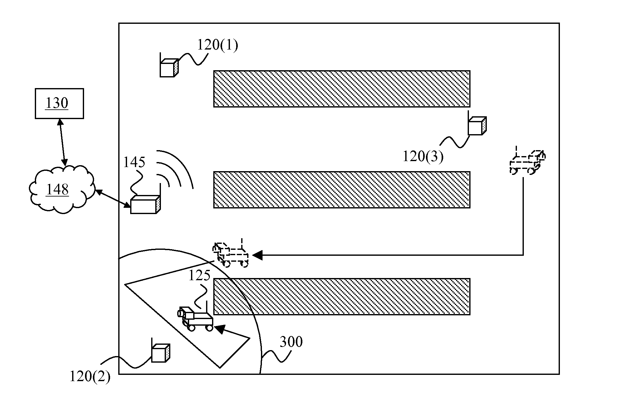
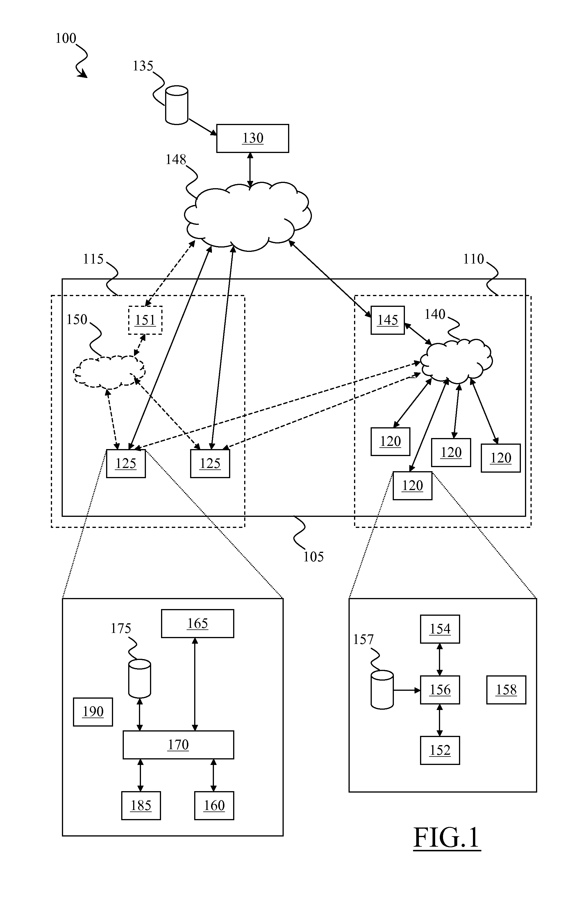
[0041]With reference to the drawings, FIG. 1 illustrates in terms of functional blocks an area monitoring system 100 according to an embodiment of the present invention. The area monitoring system 100 is configured to monitor an environmental condition of an area 105 through the measurement of a corresponding environmental quantity. For example, the area monitoring system 100 may implement a “green computing” service for the monitoring of temperature within a server farm; in this case, the area 105 to be monitored by the area monitoring system 100 is the place wherein the servers forming the server farm are physically located.

[0042]According to an embodiment of the present invention, the area monitoring system 100 includes two main sections, and specifically a static section, identified in the figure with the reference 110, and a mobile section, identified in the figure with the reference 115. The static section 110 comprises a plurality of static sensor units 120 spatially arranged...


PUM


Abstract

A monitoring system monitoring an environmental condition of an area by measuring an environmental quantity, including: a static monitoring section including plural static sensor units each configured to collect first measure data relating to the environmental quantity in respective portions of the area; a mobile monitoring section including at least one robot configured to move within the area to collect second measure data relating to the environmental quantity in a portion of the area surrounding the robot; and a central unit communicating with the static sensor units and robot to perform: conditioned to assessing an anomalous environmental condition from first measure data collected by at least one static sensor unit, commanding the robot to operate according to anomaly routines, and conditioned to assessing an anomalous environmental condition from second measure data collected by the robot, commanding at least one static sensor unit to operate according to anomaly routines.

Description

BACKGROUND OF THE INVENTION[0001]The present invention relates to the field of the automated systems for monitoring areas.DESCRIPTION OF THE RELATED ART[0002]Nowadays, the so called Internet of Things is one of the most interesting and promising subjects in the computing and telecommunications fields. With the term of “Internet of Things”, it is generally intended a networked interconnection of machines capable of making available resources that can be remotely accessed. The “machines” may be sensors, actuators, or everyday objects (such as household appliances, clothes, cars, etc.), all provided with a wired or wireless network communication capability. The “resources” may be readings of monitored parameters (e.g., readings from electricity meters, gas meters, water meters, or weather reports, traffic information, etc.), status of sensors (e.g., proximity sensors, industrial process sensors, sensors for monitoring people and patients, etc.), actuation capabilities (e.g., opening a ...

Claims


Application Information

Patent Timeline
IPC IPC(8): G01N35/00
CPCG01N35/0099G08B21/12
Inventor ANTONINI, ROBERTOFICI, GIAN PIEROGASPARDONE, MARCO
Owner TELECOM ITALIA SPA
Learn More