Touch-sensing structure and touch-sensitive device

Inactive Publication Date: 2014-02-13
WINTEK CORP
View PDF9 Cites 21 Cited by
  • Summary
  • Abstract
  • Description
  • Claims
  • Application Information

AI Technical Summary

Benefits of technology

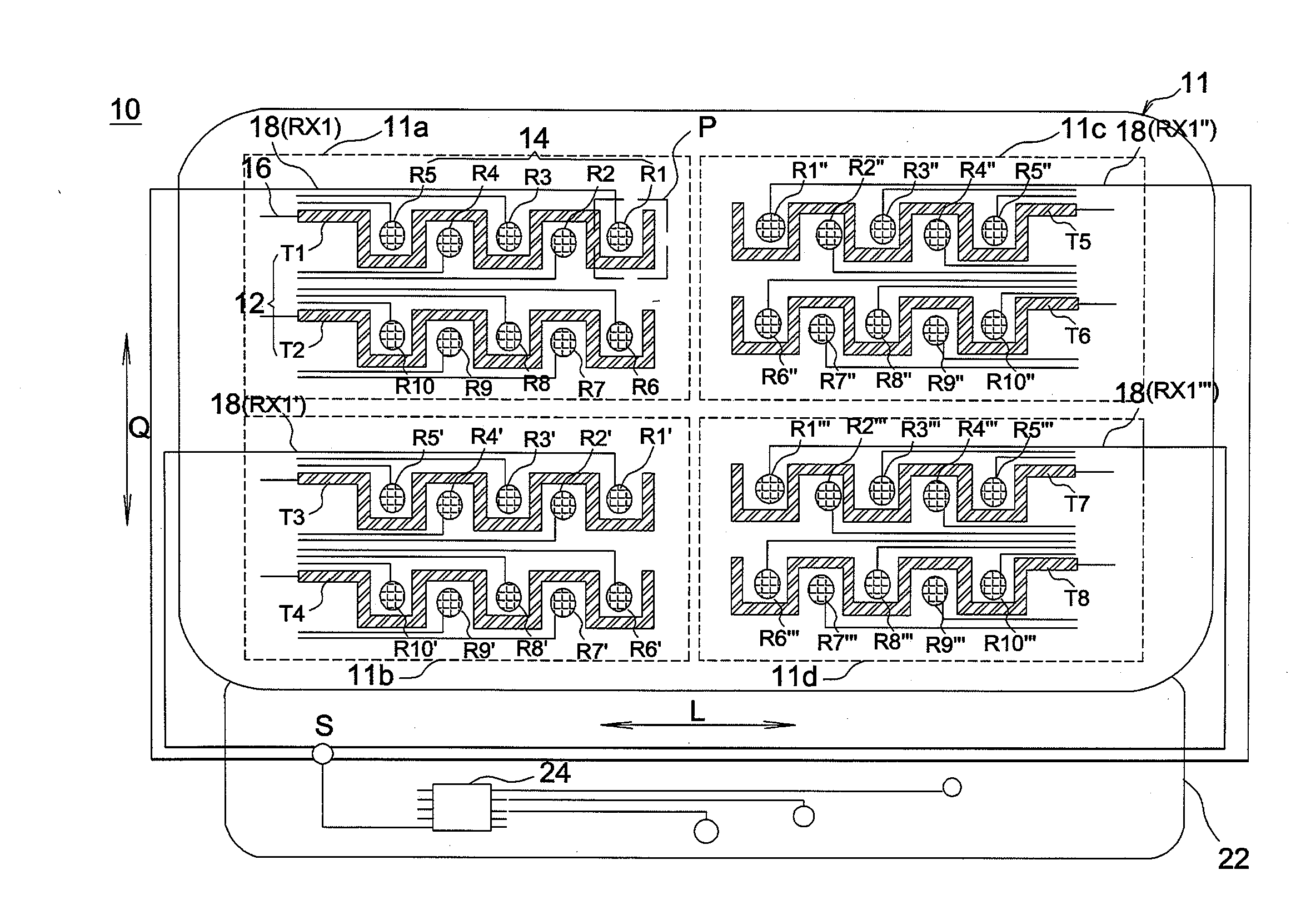
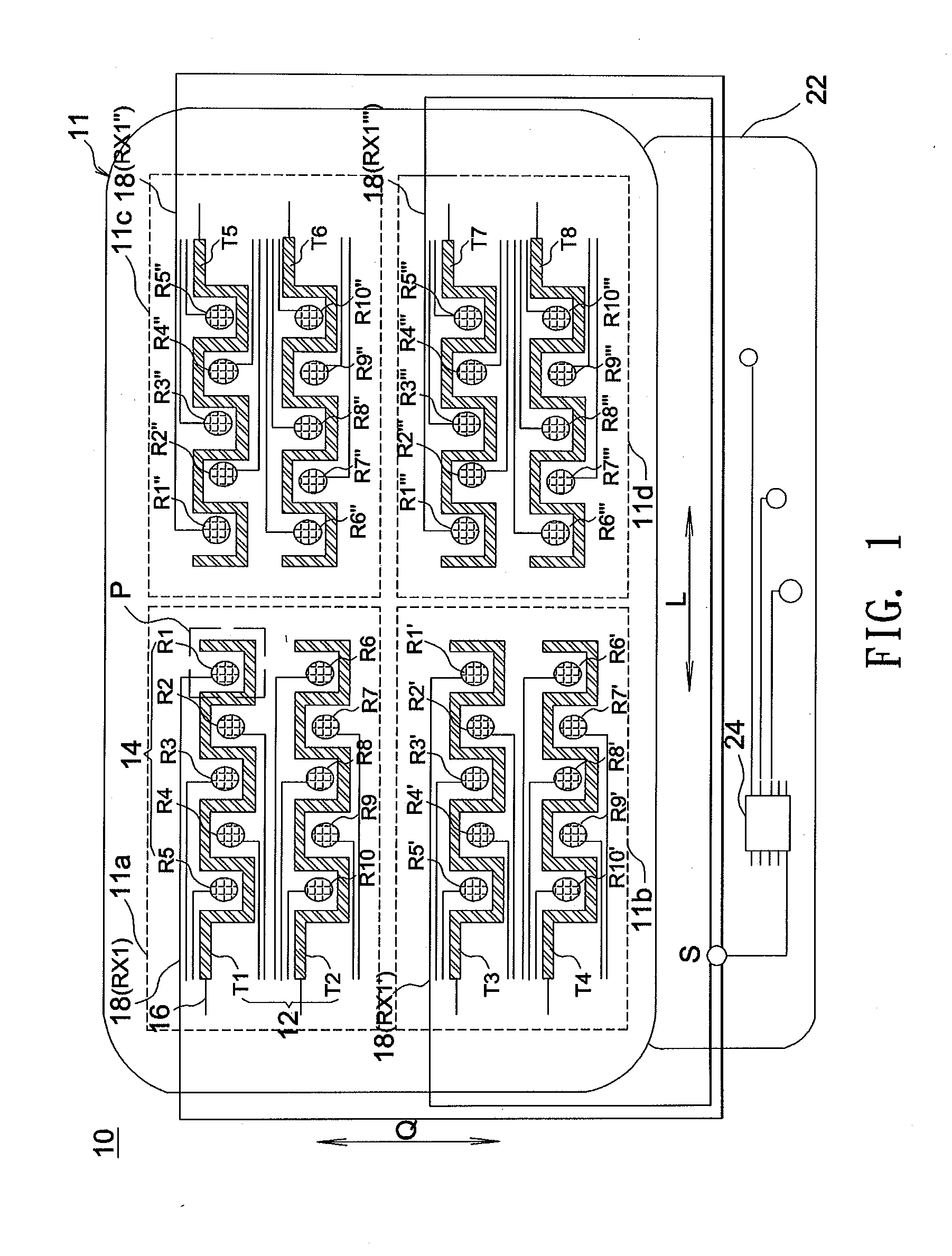
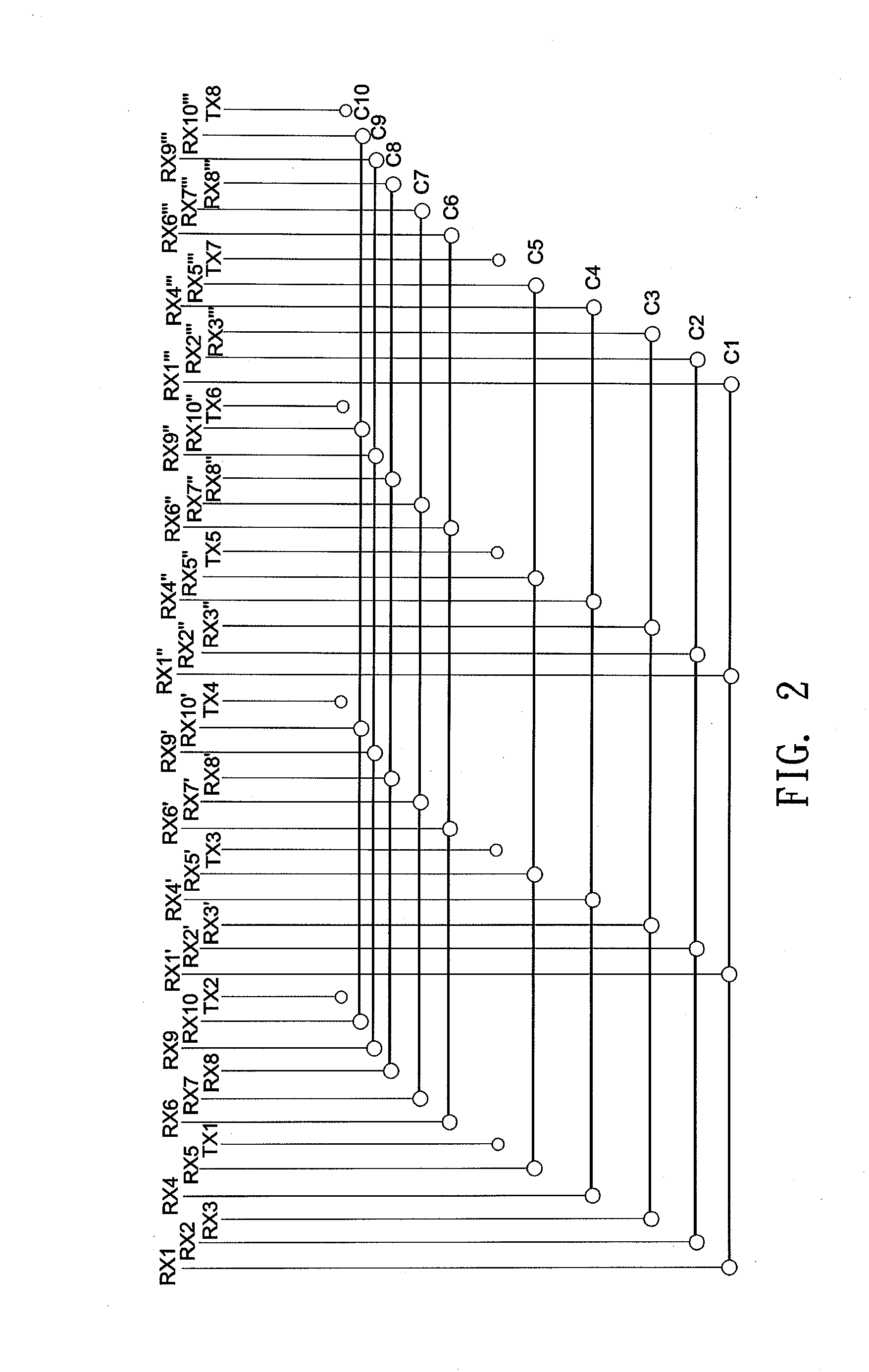
[0022]According to the above embodiments, the amount of channels needed for a single-layer touch-sen

Problems solved by technology

However, except for being complicated, such fabrication processes may cause low production yields because of the step of flipping over the glass substrate to achieve double-sided patterning.
In that case, unstable material characteristics of an organic insulation layer or other f

Method used


Image

  • Touch-sensing structure and touch-sensitive device
  • Touch-sensing structure and touch-sensitive device
  • Touch-sensing structure and touch-sensitive device

Examples


Embodiment Construction

[0038]In the following detailed description of the preferred embodiments, reference is made to the accompanying drawings which form a part hereof, and in which are shown by way of illustration specific embodiments in which the invention may be practiced. In this regard, directional terminology, such as “top,”“bottom,”“front,”“back,” etc., is used with reference to the orientation of the Figure(s) being described. The components of the invention can be positioned in a number of different orientations. As such, the directional terminology is used for purposes of illustration and is in no way limiting. On the other hand, the drawings are only schematic and the sizes of components may be exaggerated for clarity. It is to be understood that other embodiments may be utilized and structural changes may be made without departing from the scope of the invention. Also, it is to be understood that the phraseology and terminology used herein are for the purpose of description and should not be ...


PUM


Abstract

A touch-sensing structure includes a substrate and a conductive layer. The conductive layer spreads over a surface of the substrate and includes a plurality of first electrodes, a plurality of second electrodes, a plurality of first conductive lines, and a plurality of second conductive lines. The surface is divided into a plurality of regions. The second electrodes are divided into multiple second electrode groups, and each second electrode group is formed by at least one of the second electrodes in each of the regions. Each of the first conductive lines is connected to one of the first electrodes, and each of the second conductive lines is connected to one of the second electrodes. The second conductive lines connected to the second electrodes in the same second electrode group are electrically connected with each other.

Description

BACKGROUND OF THE INVENTION[0001]a. Field of the Invention[0002]The invention relates to a touch-sensing structure and a touch-sensitive device.[0003]b. Description of the Related Art[0004]Nowadays, a touch-sensing electrode structure of a capacitive touch-sensitive device is often fabricated using double-sided ITO or single-sided ITO fabrication processes. On forming conventional double-sided ITO patterns, coating, etching, and photolithography processes are performed on each of a top side and a bottom side of a glass substrate to form X-axis and Y-axis sensing electrodes on the two sides. However, except for being complicated, such fabrication processes may cause low production yields because of the step of flipping over the glass substrate to achieve double-sided patterning. In comparison, on forming conventional single-sided ITO patterns, since X-axis and Y-axis sensing electrodes are formed on the same side of a glass substrate, a bridge wiring structure needs to be formed in a...

Claims


Application Information

Patent Timeline
IPC IPC(8): H01L51/52
CPCH01L51/5203G06F3/0443G06F3/0448G06F3/04164H10K50/805
Inventor CHEN, KUO-HSINGCHEN, YU-TINGSU, KUO-CHANGSU, CHEN-HAO
Owner WINTEK CORP
Why Eureka
Try Eureka