Clamping device

a technology of clamping device and spherical plate, which is applied in the direction of manufacturing tools, transportation and packaging, coatings, etc., can solve the problem of easy scraping of workpieces

Active Publication Date: 2014-02-13
SHENZHENSHI YUZHAN PRECISION TECH CO LTD +1
View PDF12 Cites 5 Cited by
  • Summary
  • Abstract
  • Description
  • Claims
  • Application Information

AI Technical Summary

Benefits of technology

[0004]In a surface process of a workpiece, such as an anodizing process, a rack may be used for holding and positioning the workpiece. The rack may include a pair of elastic sheets for positioning a workpiece. When the workpiece needs to be placed on the rack, a robot arm holds a workpiece, and transfers the workpiece to a position adjacent to the rack latching with one of the elastic sheets. The robot arm presses the other elastic sheet until the workpiece is latched between the pair of elastic sheets. Finally, the robot arm releases the pressed elastic sheet. However, the workpiece is easily scraped during the deformation of the elastic sheet.

Problems solved by technology

However, the workpiece is easily scraped during the deformation of the elastic sheet.

Method used


Image

  • Clamping device
  • Clamping device
  • Clamping device

Examples


Embodiment Construction

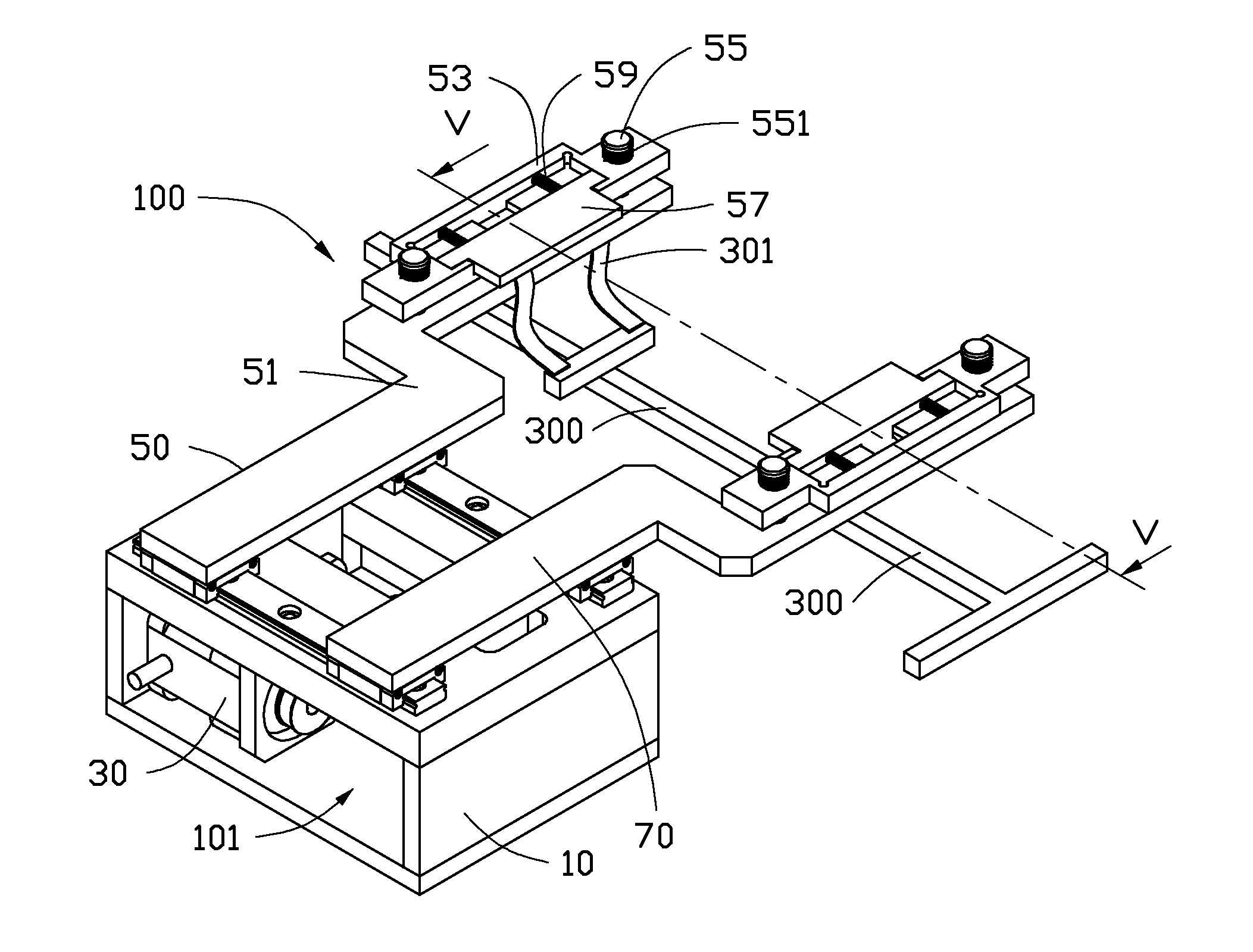
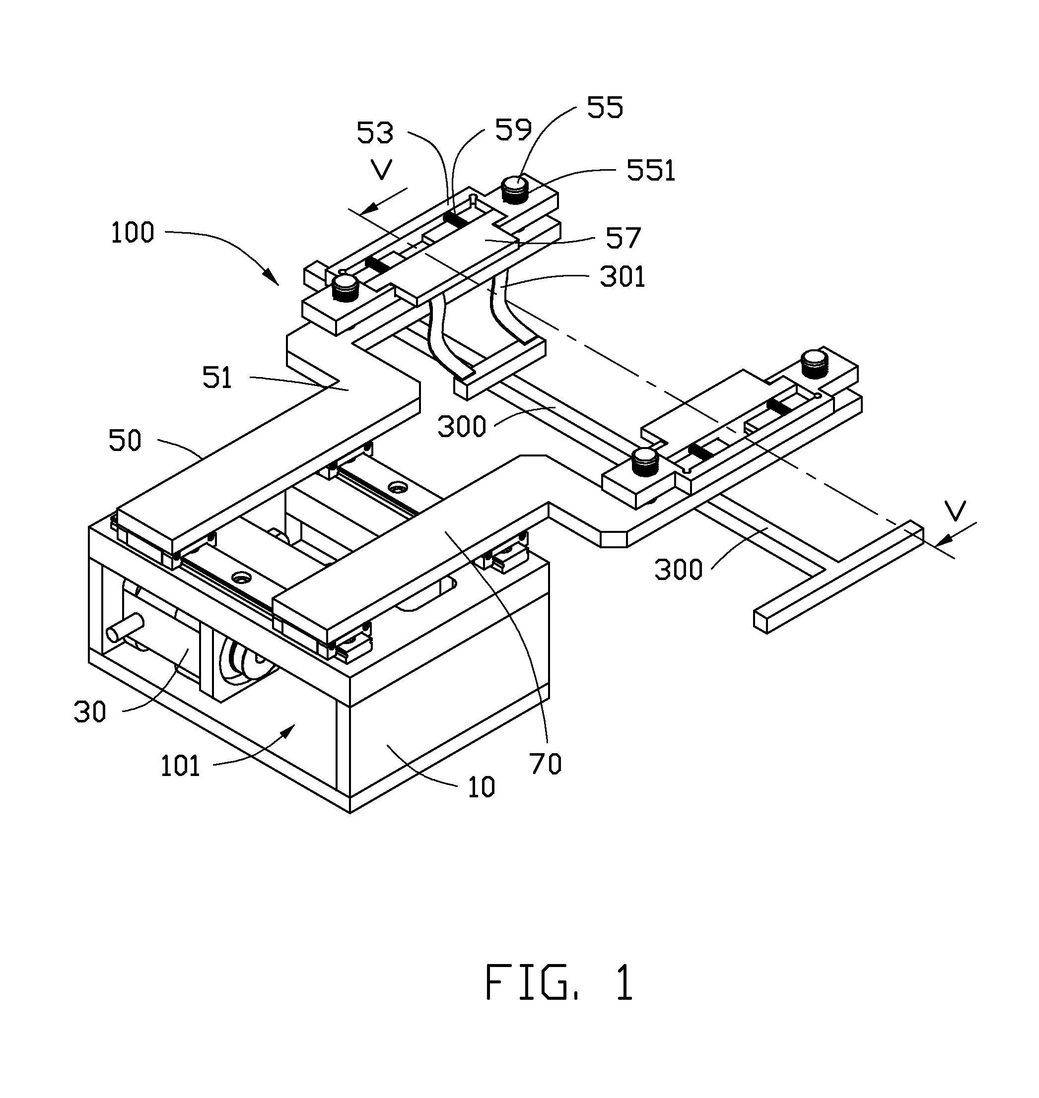
[0013]FIGS. 1 and 6 show one embodiment of a clamping device 100, for clamping and positioning a workpiece 200 to a rack 300. The rack 300 includes four bent elastic sheets 301 at opposite sides of the rack 300. Each of the elastic sheets 301 is substantially S-shaped, and includes a clamping portion 3011 and a resisting portion 3012 bent from a distal end of the clamping portion 3011. A section of the workpiece 200 is substantially U-shaped, and includes opposite inner sidewalls 201. The resisting portions 3012 of the elastic sheets 301 are capable of resisting the inner sidewalls 201 of the workpiece 200, for positioning the workpiece 200 (shown in FIG. 6).

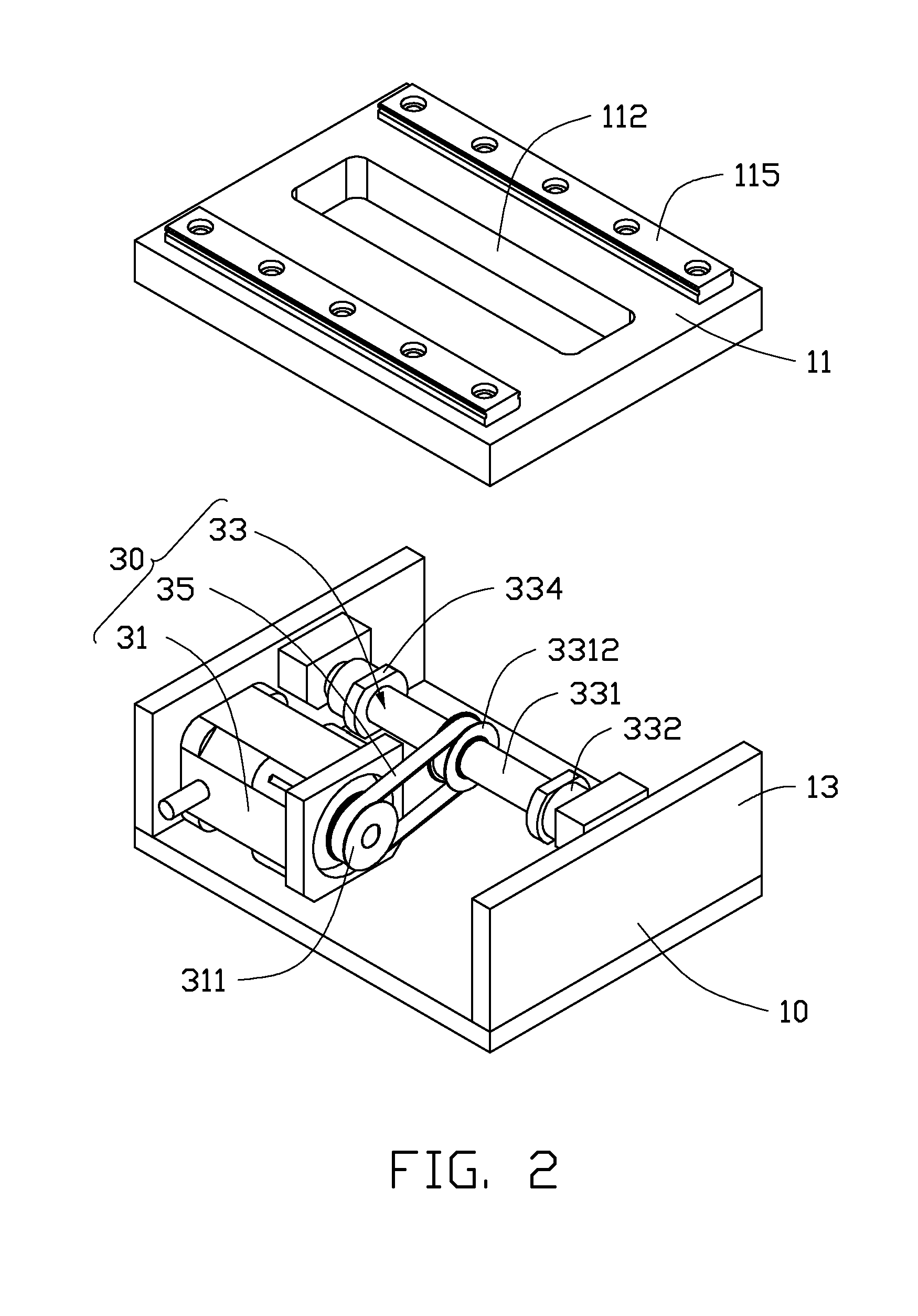
[0014]The clamping device 100 includes a mounting base 10, a driving mechanism 30, and a pair of clamping mechanisms 50. FIG. 2 shows the mounting base 10 and the driving mechanism 30. The mounting base 10 is a substantially hollow frame, and defines a receiving chamber 101. The mounting base 10 includes a mounting plate 11 and ...


PUM

PropertyMeasurementUnit
elastic resetting forceaaaaaaaaaa
resetting forceaaaaaaaaaa
distanceaaaaaaaaaa

Abstract

A clamping device includes a driving mechanism and a pair of clamping mechanisms. Each clamping mechanism includes a clipping member, an installing plate, a positioning member, a resisting plate, and an elastic member. The clipping members are movably connected to the driving mechanism. A protrusion protrudes from the clipping member, and includes a first inclined surface. The installing plate defines an opening. The protrusion passes through the opening. The positioning member is inserted into the installing plate and fixed with the clipping member. The resisting plate is movably mounted on the installing plate. An abutting portion protrudes from the resisting plate, and passes through the opening. The abutting portion comprises a second inclined surface resisting the first inclined surface, the elastic member is sandwiched between the installing plate and the resisting plate, for providing a resetting force to the resisting plate.

Description

BACKGROUND[0001]1. Technical Field[0002]The present disclosure relates to clamping devices, and particularly to a clamping device for clamping a workpiece to a rack for an anodizing process.[0003]2. Description of Related Art[0004]In a surface process of a workpiece, such as an anodizing process, a rack may be used for holding and positioning the workpiece. The rack may include a pair of elastic sheets for positioning a workpiece. When the workpiece needs to be placed on the rack, a robot arm holds a workpiece, and transfers the workpiece to a position adjacent to the rack latching with one of the elastic sheets. The robot arm presses the other elastic sheet until the workpiece is latched between the pair of elastic sheets. Finally, the robot arm releases the pressed elastic sheet. However, the workpiece is easily scraped during the deformation of the elastic sheet.[0005]Therefore, there is room for improvement in the art.BRIEF DESCRIPTION OF THE DRAWINGS[0006]The components in the ...

Claims


Application Information

Patent Timeline
Patent Type & Authority Applications(United States)
IPC IPC(8): B25J15/00
CPCB25J15/0028C25D17/06C25D11/005Y10S294/902
Inventor LI, BINGYANG, BO
Owner SHENZHENSHI YUZHAN PRECISION TECH CO LTD
Why Eureka
Try Eureka