
Image display device and image display method

a display device and image technology, applied in the field of image display devices and image display methods, can solve the problems of low light-utilization efficiency of this device, color breakage, color breakage, etc., and achieve the effect of more and effective suppression of color breakag

Inactive Publication Date: 2014-02-13
SHARP KK
View PDF3 Cites 5 Cited by
  • Summary
  • Abstract
  • Description
  • Claims
  • Application Information

AI Technical Summary

Benefits of technology

The patent text describes an image display device that uses a field-sequential system and a system for controlling brightness of a light source for each area. The device can show mixed-color displays in each sub-frame period, which helps to suppress color breakup and avoid the need for a time division system. The device also sets an achromatic sub-frame for achromatic display and allows for easy adjustment of hue angle and chromaticness. Overall, the device provides more effective suppression of color breakup and improves the quality of display.

Problems solved by technology

However, because about two thirds of light of a backlight irradiated to a liquid crystal panel are absorbed by the color filter, a liquid crystal display device of a color filter system has a problem in that light-utilization efficiency of this device is low.
However, a field sequential color system has a problem in that color breakup (color break) occurs in this system. FIG. 31 is diagram showing a principle of occurrence of color breakup.

Method used


Image

  • Image display device and image display method
  • Image display device and image display method
  • Image display device and image display method

Examples


first embodiment

1. First Embodiment

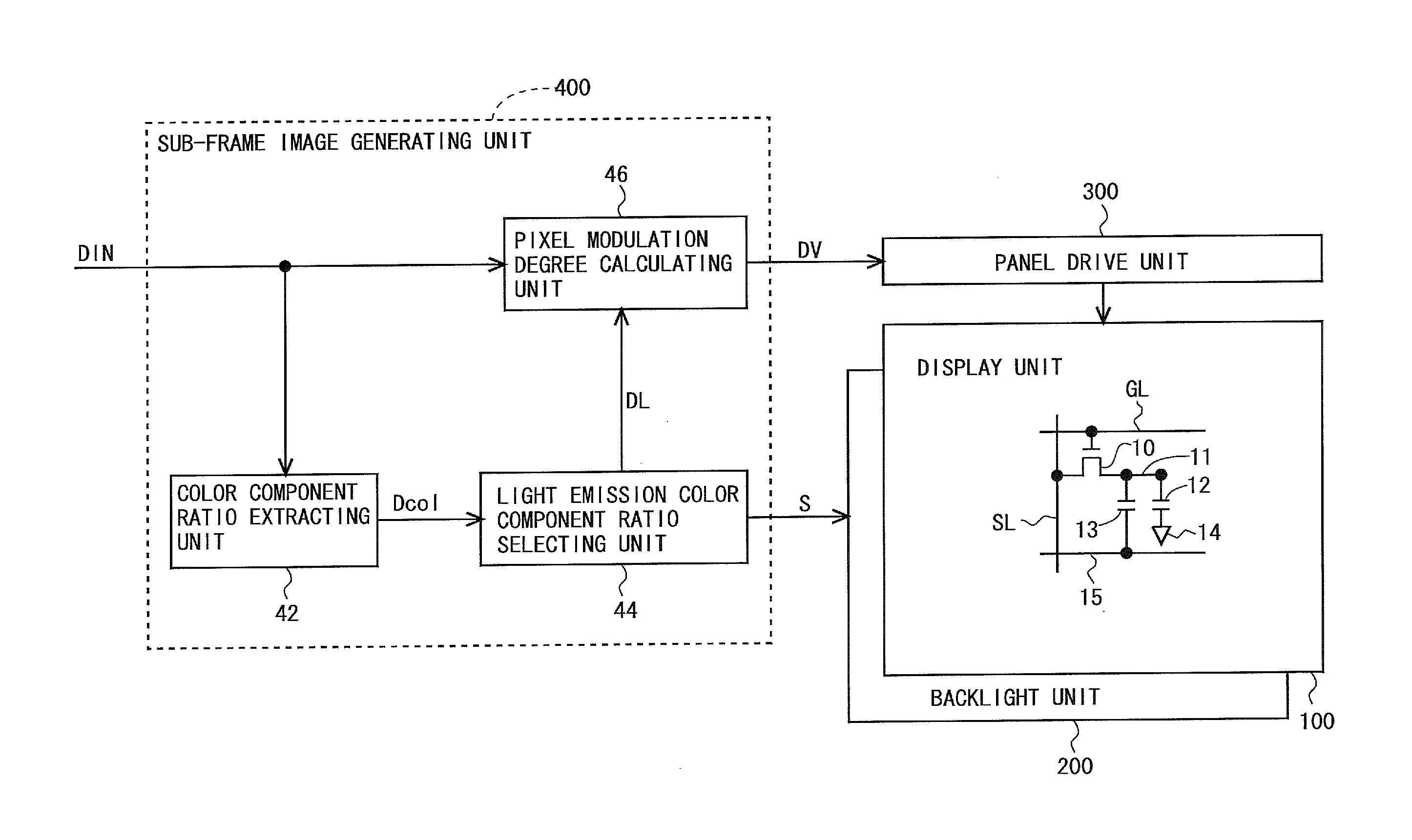
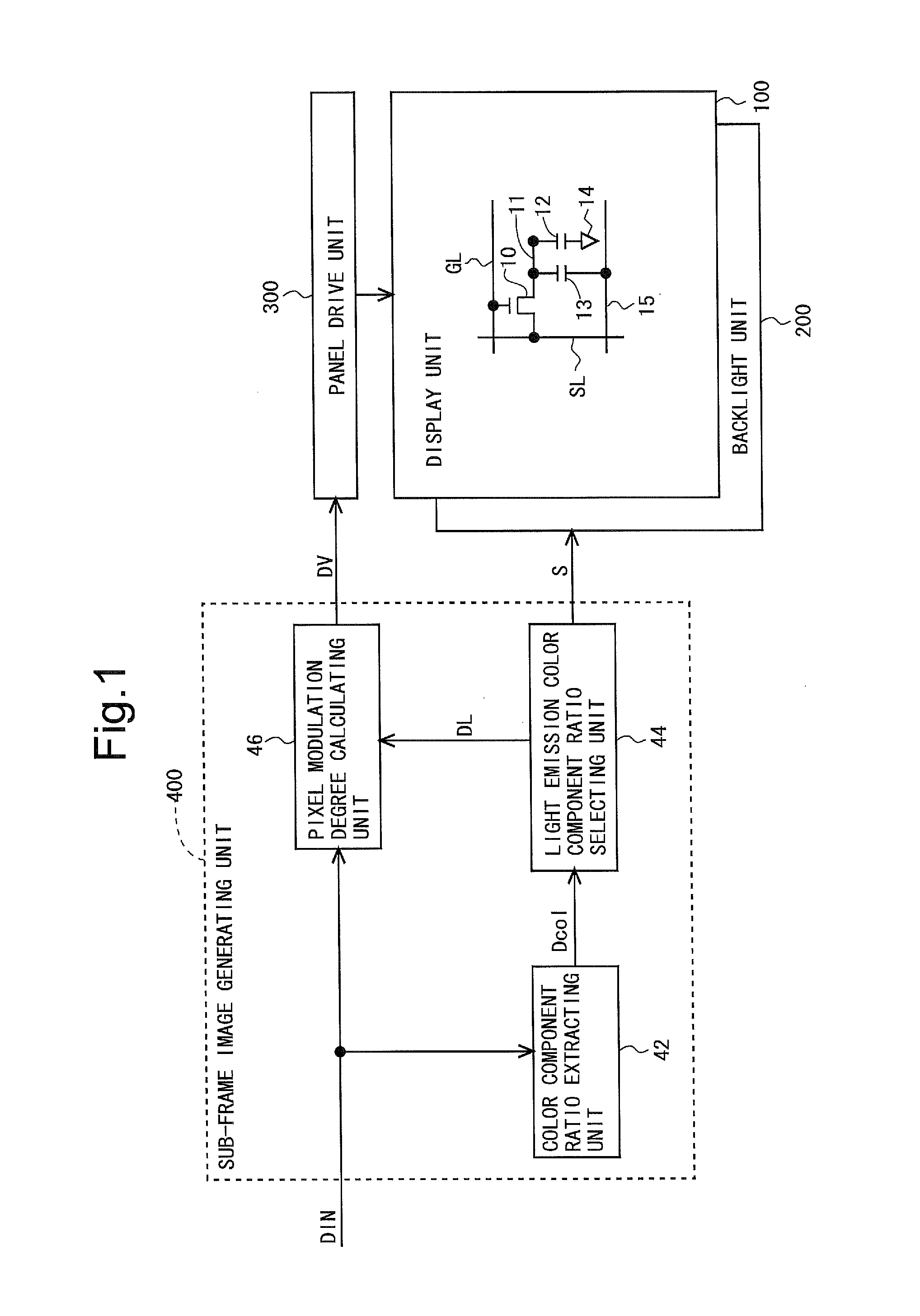
[0089]FIG. 1 is a block diagram showing an overall configuration of a liquid crystal display device according to a first embodiment of the present invention. This liquid crystal display device is configured by a display unit 100, a backlight unit 200, a panel drive circuit 300, and a sub-frame image generating unit 400. The sub-frame image generating unit 400 has a color component ratio extracting unit 42, a light emission color component ratio selecting unit 44, and a pixel modulation degree calculating unit 46. It should be noted that, in the present embodiment, a light irradiating unit is realized by the backlight unit 200.

[0090]In the display unit 100, a plurality of source bus lines (video signal lines) SL and a plurality of gate bus lines (scanning signal lines) GL are arranged. A pixel formation portion for forming a pixel is provided at the respective intersections of the source bus lines SL and the gate bus lines GL. That is, the display unit 100 includes...

second embodiment

2. Second Embodiment

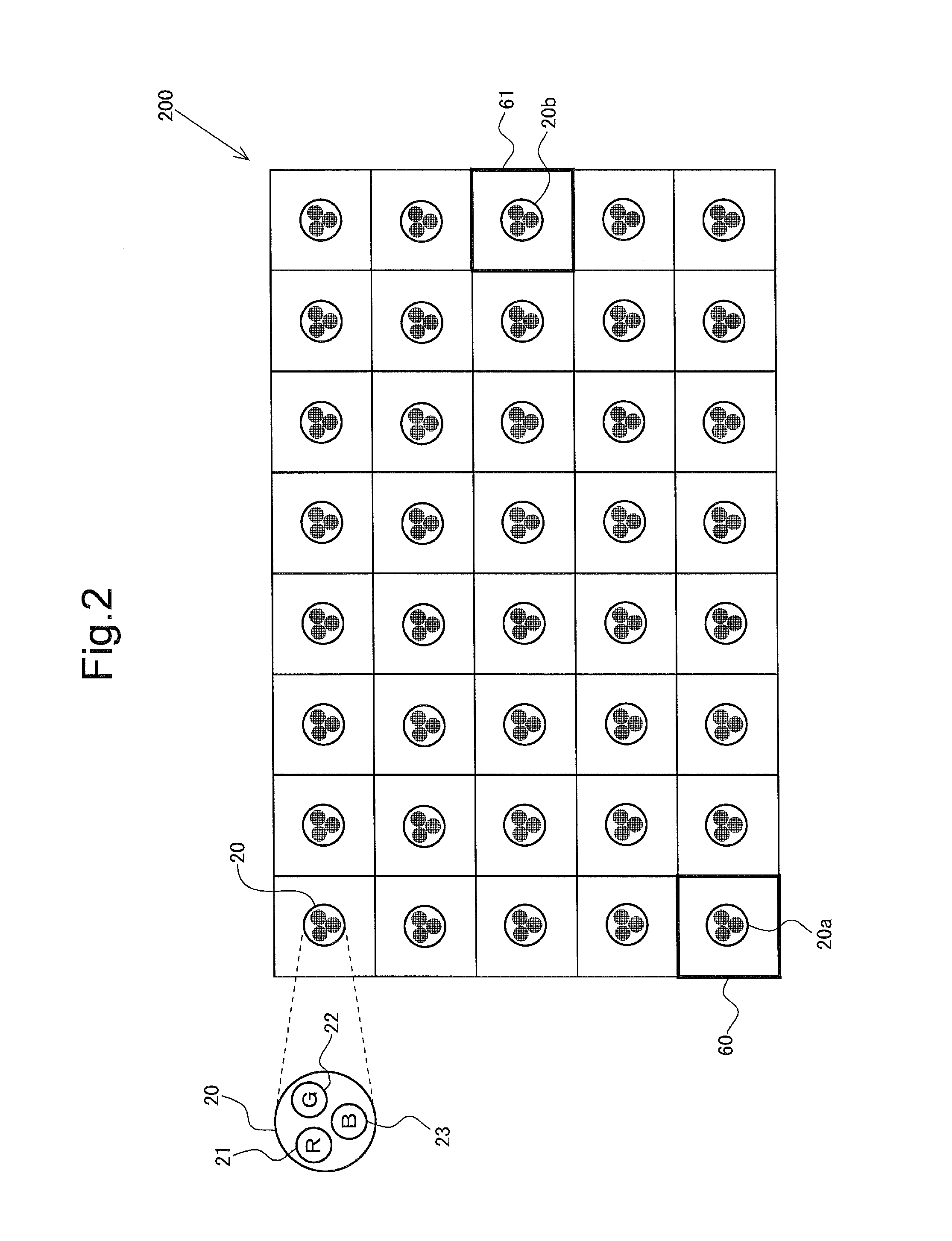
[0137]A total configuration of a liquid crystal display device, a configuration of the backlight unit 200, and a configuration of a pixel area in the display unit 100 are similar to those in the first embodiment. Therefore, their descriptions are omitted (see FIG. 1 to FIG. 3). Like in the first embodiment, one frame period is configured by a plurality of sub-frames (four sub-frames in the present description). However, as described later, unlike in the first embodiment, one of a plurality of sub-frames (first sub-frame in the present description) is set as a sub-frame for performing achromatic display (hereinafter, also referred to as an “achromatic sub-frame”). Sub-frames other than the achromatic sub-frame are set as sub-frames for performing chromatic display (hereinafter, also referred to as “chromatic sub-frames”). That is, in the present embodiment, as shown in FIG. 22, one frame period is configured by the first sub-frame as an achromatic sub-frame and se...


PUM

PropertyMeasurementUnit
colorsaaaaaaaaaa
color component ratioaaaaaaaaaa
light emission color component ratioaaaaaaaaaa

Abstract

An image display device is disclosed, using a field-sequential system capable of more effectively suppressing occurrence of color breakup. The image display device includes a color component ratio extracting unit that extracts a color component ratio for reproducing a target display color included in a target image as a light emission color component ratio candidate, and a light emission color component ratio selecting unit that selects a light emission color component ratio (a color component ratio when LEDs of a plurality of colors included in an LED unit emit light) in each sub-frame period from among light emission color component ratio candidates extracted by the color component ratio extracting unit. To enable mixed-color display in all sub-frame periods, each LED is controlled to be able to take any light emission state of either a lighting-on state or a lighting-off state in each sub-frame period.

Description

TECHNICAL FIELD[0001]The present invention relates to an image display device and an image display method, and relates more particularly to a technique for suppressing occurrence of color breakup in an image display device using a field-sequential system.BACKGROUND ART[0002]Many of liquid crystal display devices that perform color display include a color filter for transmitting light of a red color (R), a green color (G), and a blue color (B), for each sub-pixel obtained by dividing one pixel into three sub-pixels. However, because about two thirds of light of a backlight irradiated to a liquid crystal panel are absorbed by the color filter, a liquid crystal display device of a color filter system has a problem in that light-utilization efficiency of this device is low. Then, a liquid crystal display device of a field-sequential system that performs color display without using a color filter is being focused.[0003]In the field-sequential system, a display period for one screen (one ...

Claims


Application Information

Patent Timeline
Patent Type & Authority Applications(United States)
IPC IPC(8): G06T11/00
CPCG06T11/001G09G3/2022G09G3/3413G09G3/3426G09G2300/0876
Inventor ISHIHARA, TOMOYUKI
Owner SHARP KK
Learn More