Method and apparatus for detecting track failure

a technology of track failure and detection method, applied in the direction of structural/machine measurement, material thermal analysis, material flaw investigation, etc., can solve problems such as rail failure alerts, and achieve the effect of quick identification of faults

Active Publication Date: 2014-02-13
HARRISON HAROLD
View PDF4 Cites 13 Cited by
  • Summary
  • Abstract
  • Description
  • Claims
  • Application Information

AI Technical Summary

Benefits of technology

[0011]The present invention is a system and method for quickly identifying faults induced in railroad track sections caused by temperature changes or mechanical failures. The methods described herein enable reliable alarming in real time by detecting a sudden change in RNT. In the context of the invention, the time frame for detecting a change in RNT is approximately ten minutes or less, whereas the prior art systems commonly required hours or even days of collecting data to reliably detect failures.

Problems solved by technology

If the difference exceeds a threshold, the system issues a rail failure alert.

Method used


Image

  • Method and apparatus for detecting track failure
  • Method and apparatus for detecting track failure
  • Method and apparatus for detecting track failure

Examples


Embodiment Construction

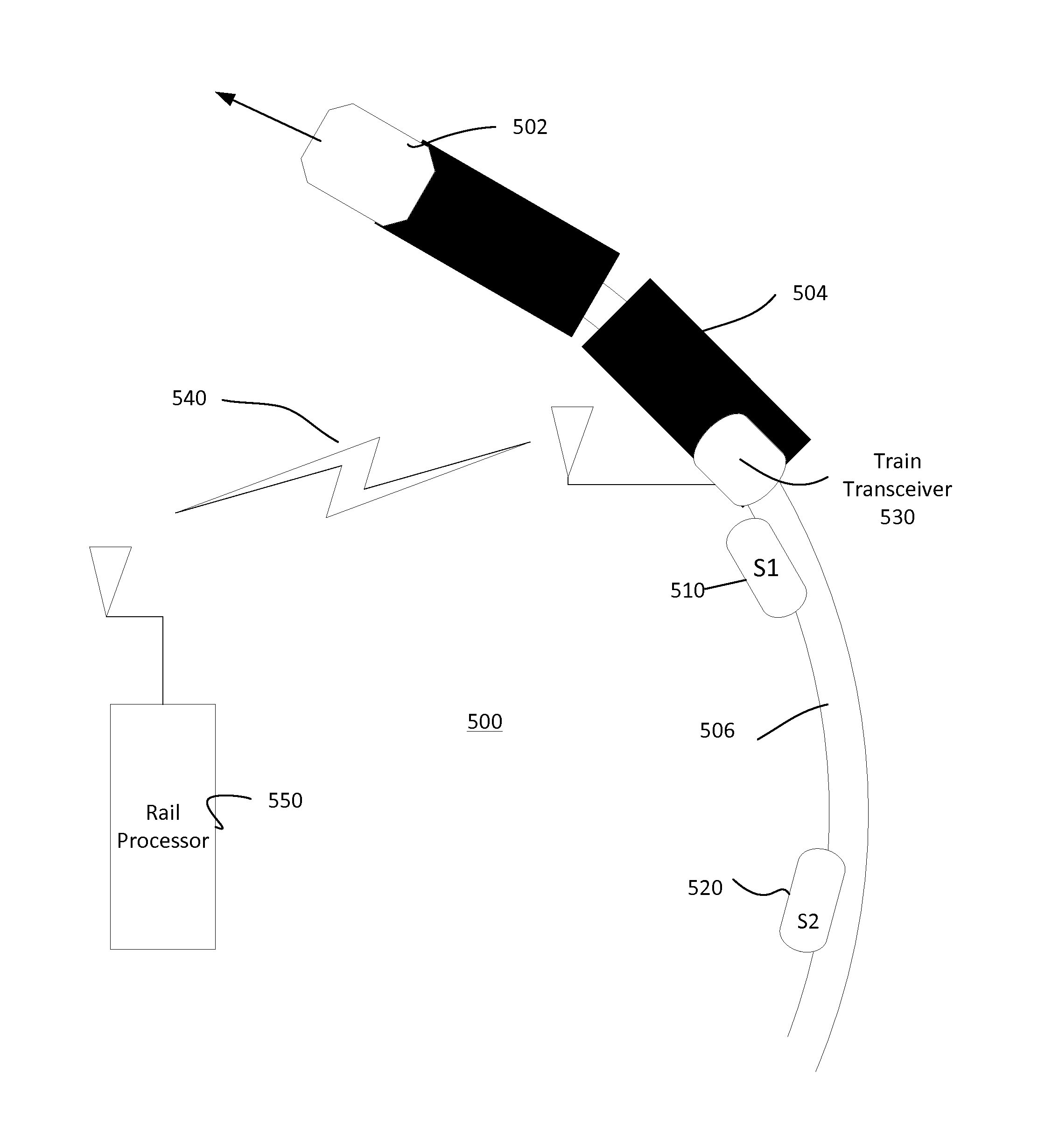
[0026]Now with reference to the FIGUREs, if an array of data sensors is distributed along the rail track, the inventors have observed that any two adjacent sensors will detect a failure condition in the vicinity of the sensors. In prior systems, a single point failure of any one sensor may induce a jump of signal away from the RNT condition, which is counter to expectations. If the jump emulates the track failure, a false alarm might result. But if two sensors see the same jump condition at the same time, then there is a high probability that the jumps are valid alarms, even if the jumps are not of the same magnitude.

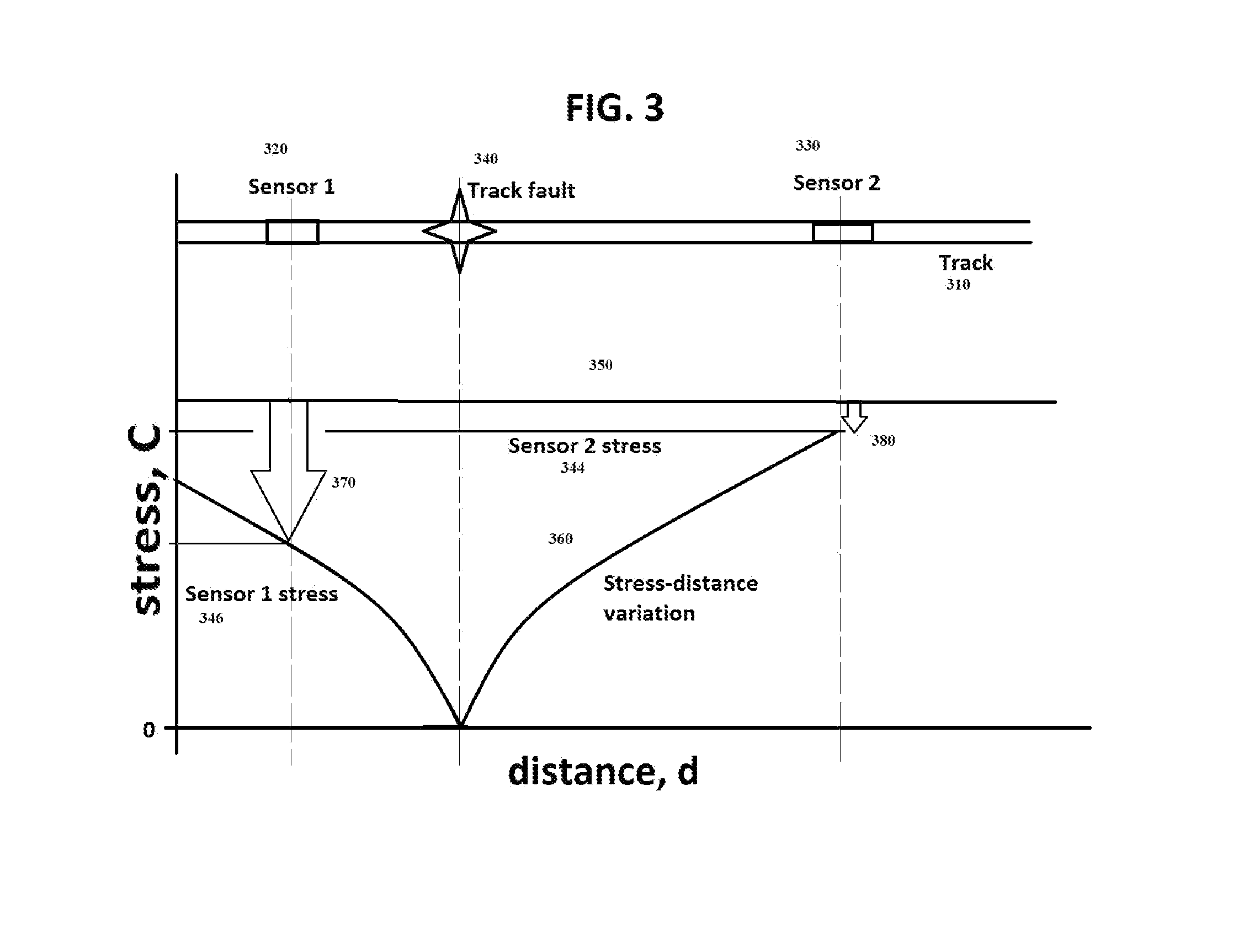
[0027]FIG. 3 illustrates the detection by two sensors 320, 330 of the same track fault 340, which is a rail break fault in this example. Prior to the fault, each of sensor 1320 and sensor 2330 are installed on track portion 310. Just prior to the fault, each of the sensors 320, 330 sense a similar stress in the rail at the then-existing track temperature. When the track...


PUM

PropertyMeasurementUnit
timeaaaaaaaaaa
longitudinal stressaaaaaaaaaa
temperatureaaaaaaaaaa

Abstract

A railroad track monitoring system is described which detects changes in rail track geometry that could lead to derailments, The changes in geometry are detected via analysis of temperature and stress parameters that are collected at one or more sensors installed on the track. Methods are described which provide faster detection and reduced false alerts, thereby saving time and expense to the railroad system.

Description

BACKGROUND OF THE INVENTION[0001]Monitoring railroad track safety and performance by sensing the Rail Neutral Temperature (RNT) or Stress Free Temperature (SFT) is known in the art. U.S. Pat. No. 7,502,670 entitled “System and Method for Determining Rail Safety Limits, for example, discusses methods of monitoring the RNT at a single point over a long period of time to determine changes in track geometry and strength. U.S. Pat. No. 7,502, 670 and the related U.S. Pat. No. 7,869,909 are incorporated by reference.[0002]FIG. 1 illustrates the concept of RNT and SFT over a range of temperatures, along the x axis, and mechanical stress, along the y axis, in graph 100. In this description, both rail stress and temperature are dimensioned in degrees Celsius. The RNT 115 is defined as the rail temperature at which the rail experiences zero stress. Rail temperatures above the RNT tend to create compression in a constrained rail. Rail temperatures below the RNT tend to create tension in a cons...

Claims


Application Information

Patent Timeline
Patent Type & Authority Applications(United States)
IPC IPC(8): G01N25/72
CPCG01N25/72G01M5/0025B61L23/044B61L23/047G01M5/0041
Inventor HARRISON, HAROLD
Owner HARRISON HAROLD
Why Eureka
Try Eureka