System and Method for Efficiently Operating Multiple Flywheels

Active Publication Date: 2014-02-13
CATERPILLAR INC
View PDF38 Cites 21 Cited by
  • Summary
  • Abstract
  • Description
  • Claims
  • Application Information

AI Technical Summary

Problems solved by technology

Consequently, the amount of energy that can be captured by an upstream-located flywheel may be reduced by the mechanical losses as it travels through the transmission and other mechanical connections, thereby decreasing the efficiency of the flywheel.
During start up, however, the drivetrain may not be configured to spin up the flywheel during machine start up.
Additionally, the location of the flywheel downstream of the transmission may make such spin up inefficient due to mechanical loss through the transmission.
Both the engine flywheel and the storage flywheel are positioned upstream of the transmission, and therefore suffer from the drawbacks noted above.
The flywheel of Bowman et al. is not coupled to the engine, and therefore is incapable of en

Method used


Image

  • System and Method for Efficiently Operating Multiple Flywheels
  • System and Method for Efficiently Operating Multiple Flywheels
  • System and Method for Efficiently Operating Multiple Flywheels

Examples


Embodiment Construction

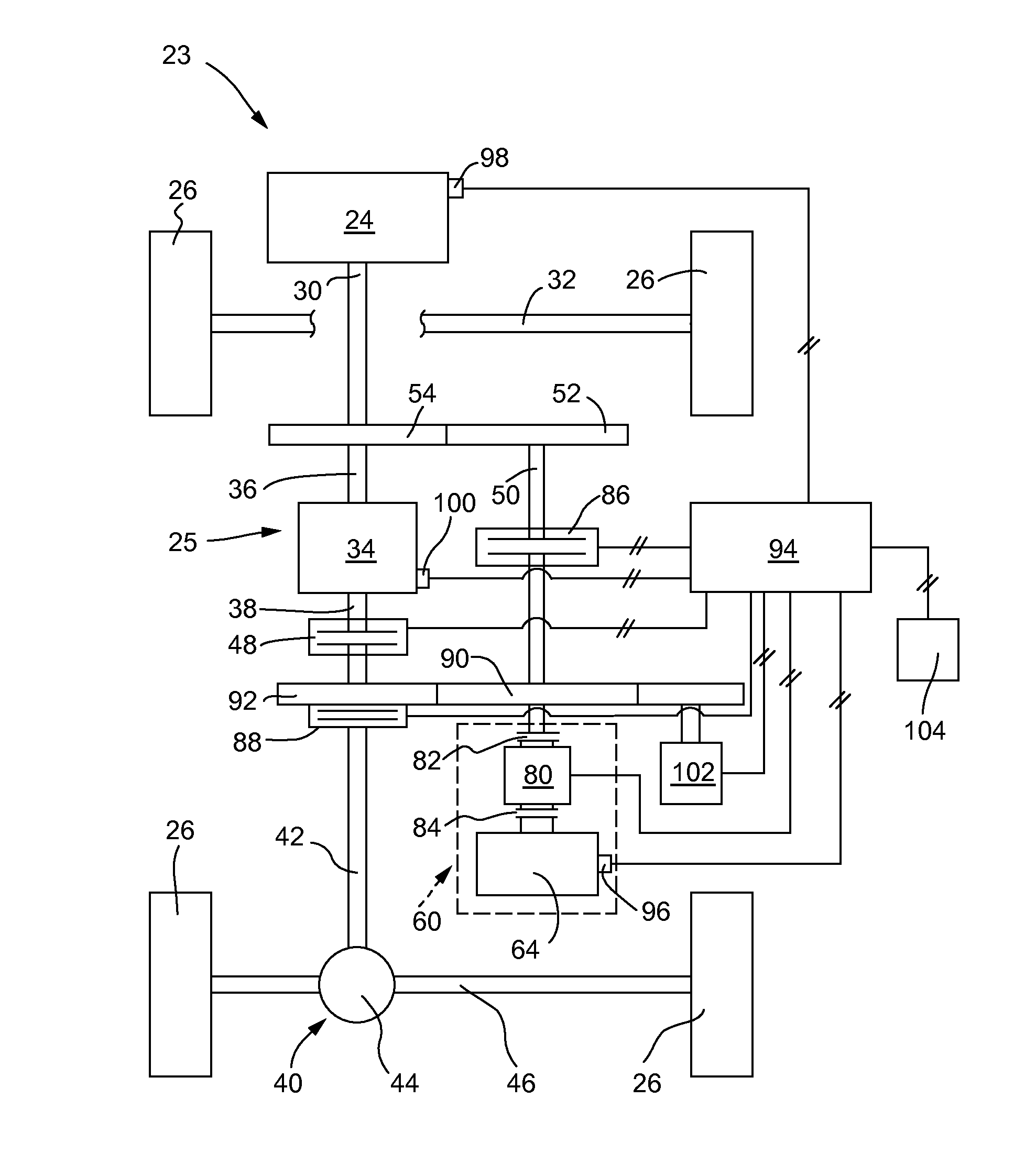
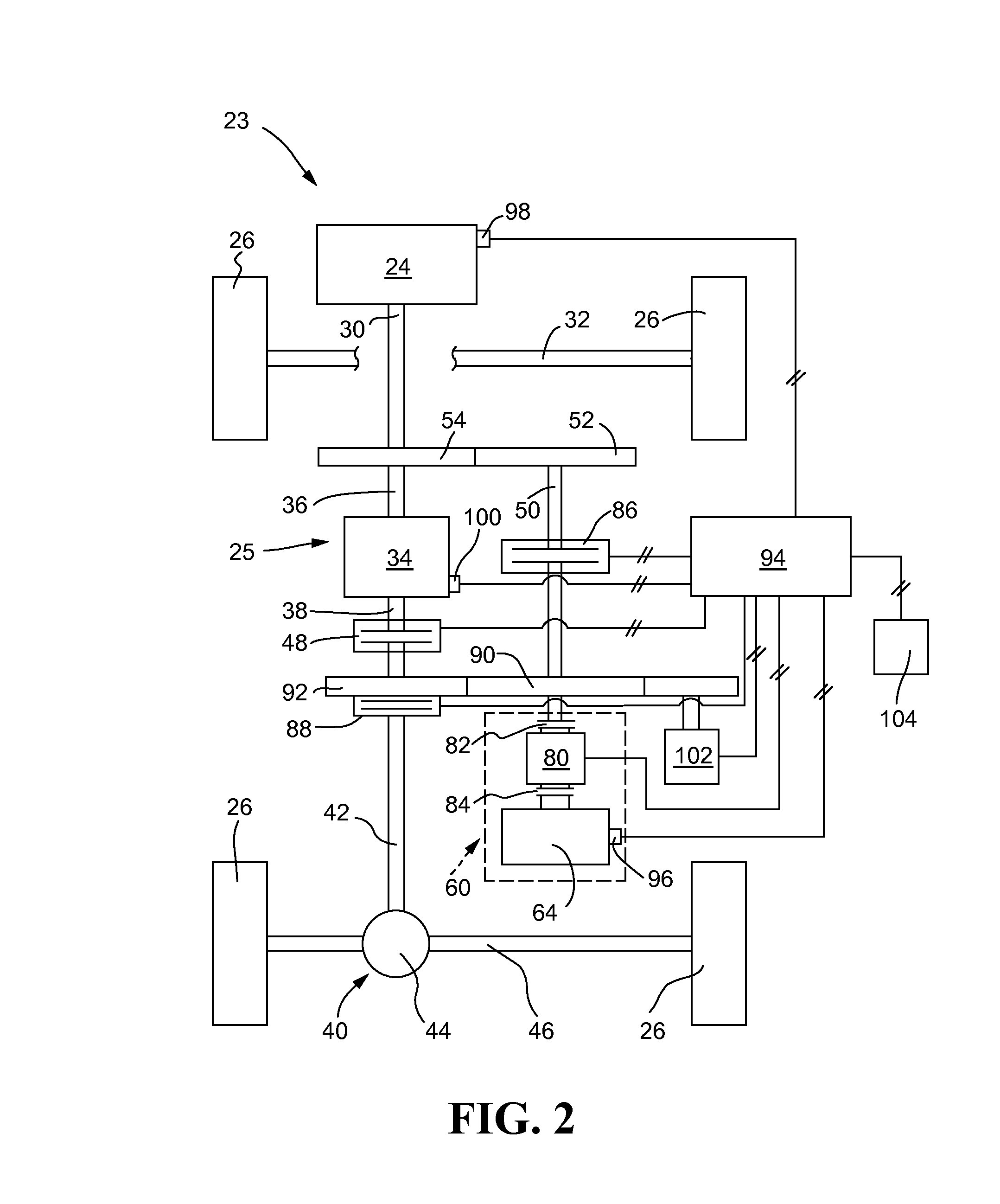
[0017]Embodiments of a flywheel assembly are disclosed for use with a machine having an engine. In some embodiments, the flywheel assembly may be used with a drivetrain configured to provide alternative points at which the flywheel may be connected to the drivetrain. For example, the drivetrain may be configured to allow the flywheel to be coupled both upstream and downstream of a transmission that may be operably coupled to the engine. The alternative connection points may increase flywheel efficiency during different modes of powertrain operation by allowing the operator to choose a connection point that minimizes mechanical loss for a given mode. In certain modes of operation, such as during initial “spin up” of the flywheel during start-up of the machine, it may be advantageous to directly connect the flywheel to the engine and bypass the transmission to reduce the amount of mechanical loss during such operation. In other modes of operation, such as during regenerative braking, ...


PUM


Abstract

A flywheel assembly may include first and second flywheels having respective first and second flywheel parasitic load profiles. Operating speeds of the first and second flywheels may be selected based at least in part on the first and second flywheel parasitic loads. The operating speeds may be determined such that an aggregate of the first and second flywheel parasitic loads is minimized, thereby increasing the efficiency of the flywheel assembly.

Description

TECHNICAL FIELD[0001]The present disclosure generally relates to flywheel energy storage devices, and more particularly to systems and methods for efficiently storing and deploying energy from flywheel assemblies provided on machines.BACKGROUND[0002]Flywheels are generally known in the art for storing energy. While flywheel energy storage devices have been used for many years in satellite or other spacecraft applications, more recently they have been adapted for use on terrestrial machines. More specifically, hybrid power plants have been proposed which use a combustion engine as the primary mover and a flywheel as a secondary mover.[0003]In some applications, the flywheel is operably coupled directly to an engine output, such as a crankshaft, upstream of a transmission. The flywheel may add to or subtract from power supplied by the engine to the transmission and, ultimately, one or more driven wheels. In this arrangement, the flywheel may also be configured to use regenerative brak...

Claims


Application Information

Patent Timeline
IPC IPC(8): G05B11/32G06F17/00
CPCB60K6/105B60W2300/17B60Y2200/142B60L50/61Y02T10/62Y02T10/70G05B11/32G06F17/00Y02T10/7072
Inventor SIEGEL, BRYAN THOMASJACOBSON, EVAN EARLO'DONNELL, TIMOTHY MICHAEL
Owner CATERPILLAR INC
Why Eureka
Try Eureka