Multi-joint robot with both-side supported arm member

a robot and arm member technology, applied in the field of multi-joint robots, can solve the problems of increasing manufacturing costs, breaking the sand die to scrape out sand,

Inactive Publication Date: 2014-02-20
FANUC LTD
View PDF18 Cites 25 Cited by
  • Summary
  • Abstract
  • Description
  • Claims
  • Application Information

AI Technical Summary

Benefits of technology

[0013]These object, feature and advantage, and other objects, features and advantages of the present invention will become more appa

Problems solved by technology

However, in the sand casting, after casting, the sand die is broken to scrape out the sand.
For this reaso

Method used


Image

  • Multi-joint robot with both-side supported arm member
  • Multi-joint robot with both-side supported arm member
  • Multi-joint robot with both-side supported arm member

Examples


first embodiment

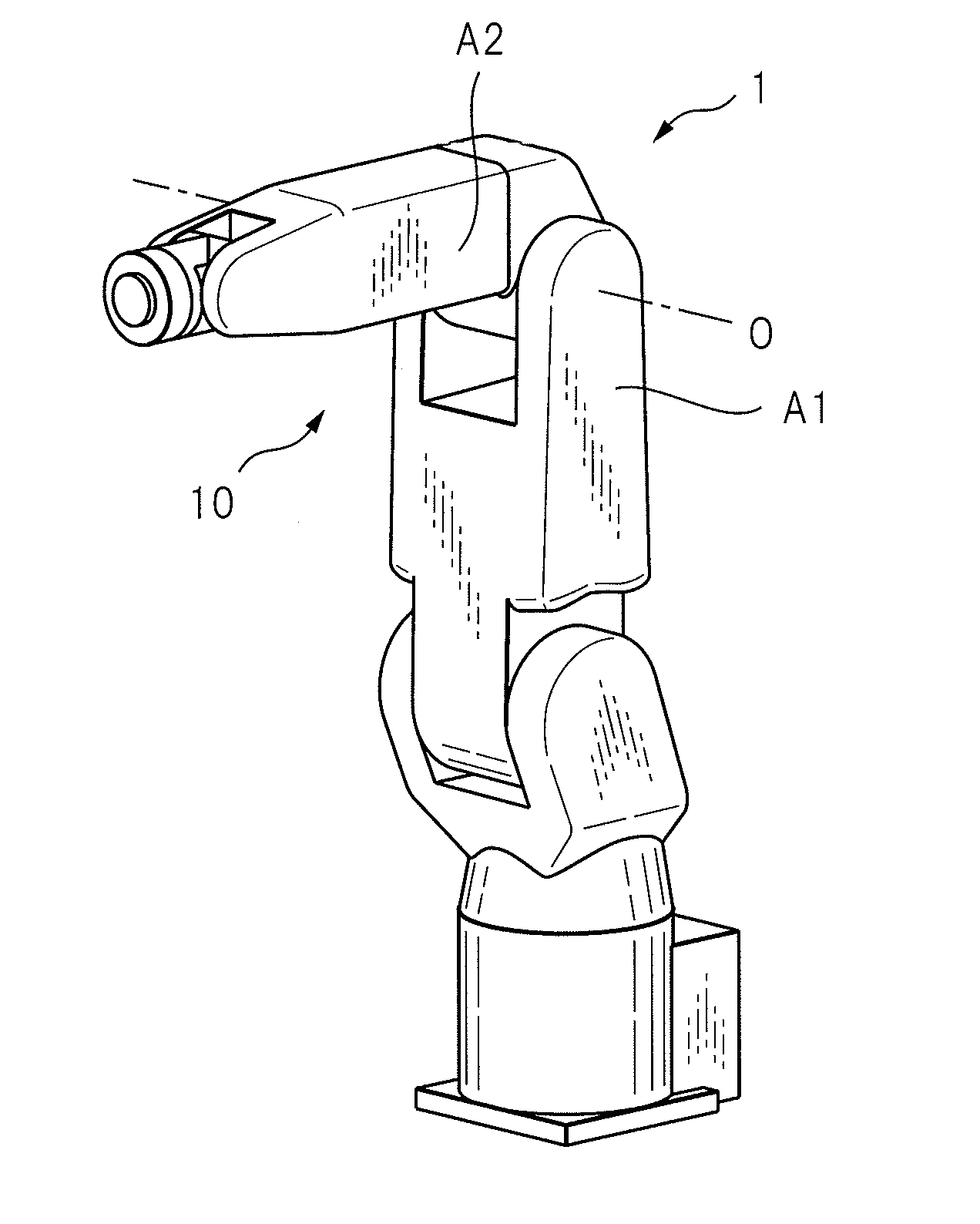
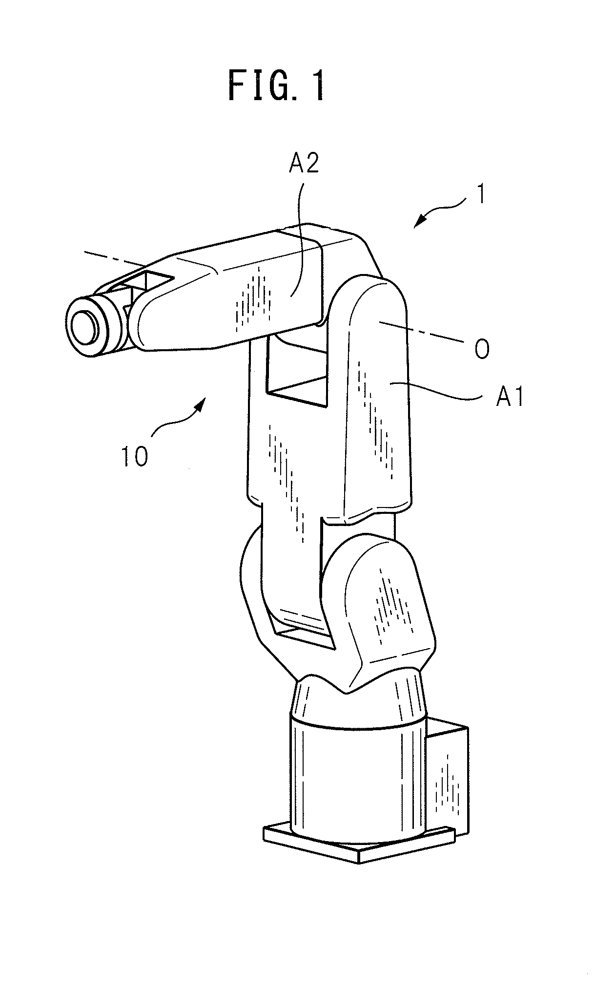
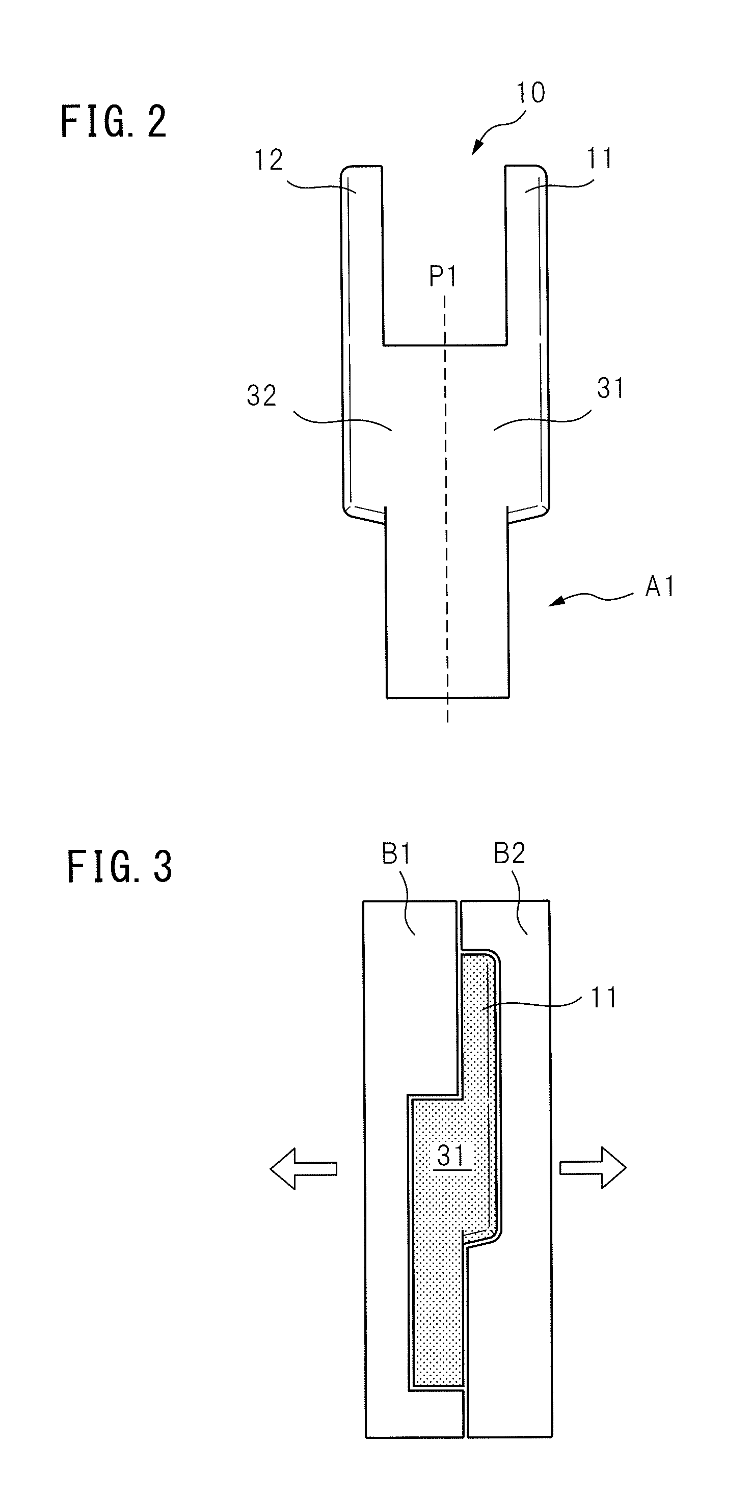
[0032]FIG. 2 is an elevation of the first arm member based on the present invention. The U-shaped portion 10 of the first arm member A1 includes two protrusion units 11 and 12 parallel with each other. In FIG. 2, at a center between these protrusion units 11 and 12, a plane P1 is illustrated. This plane P1 extends in a direction approximately perpendicular to the rotational axis O (refer to FIG. 1) of the second arm member A2. Two portions formed by dividing the first arm member A1 with the plane P1 are called half form portions 31 and 32.

[0033]FIG. 3 is a sectional view of dies for one of the half form portions that constitutes the first arm member, and according to the first embodiment, the half form portions 31 and 32 are formed by die casting. In FIG. 3, the dies B1 and B2 for the one half form portion 31 are illustrated. The boundary plane between the dies B1 and B2 is at the position corresponding to an inner wall of the protrusion unit 11. When the dies B1 and B2 are thus arr...

second embodiment

[0035]FIG. 5 is an elevation of the first arm member based on the present invention. In FIG. 5, in addition to the above-described plane P1, the additional planes P2 and P3 that pass through approximately the middle positions of the protrusion units 11 and 12 are illustrated respectively. As can be seen from the drawing, these additional planes P2 and P3 are parallel with the plane P1. Four portions formed by dividing the first arm member A1 with the plane P1 and the additional planes P2 and P3 are called half form sub-portions 41a, 41b, 42a and 42b. Moreover, it would be understood that the two half form sub-portions 41a and 41b correspond to the half form portion 31, and the two half form sub-portions 42a and 42b correspond to the half form portion 32.

[0036]FIG. 6 is a sectional view of dies for the one half form sub-portion that constitutes the first arm member, and according to the second embodiment, the half form sub-portion 41a is formed by die casting. In FIG. 6, dies B3 and ...


PUM


Abstract

In a multi-joint robot (1) including a first arm member (A1) providing a U-shaped portion (10) composed of two protrusion units (11, 12) parallel with each other, and including a second arm member (A2) connected to two protrusion units of the U-shaped portion so as to be rotated and such that both sides of the second arm member are supported by two protrusion units, the first arm member is formed by two half form portions (31, 32) that are divided between the two protrusion units of the U-shaped portion and are divided on a plane perpendicular to a rotational axis of the second arm member. Moreover, the first arm member includes a coupling unit (45a, 45b) for coupling two half form portions to each other.

Description

BACKGROUND OF THE INVENTION[0001]1. Field of the Invention[0002]The present invention relates to a multi-joint robot that includes a both-side supported arm member.[0003]2. Description of the Related Art[0004]A multi-joint robot including a plurality of joints is widely used. A general multi-joint robot includes a first arm member including a U-shaped portion, and a second arm member connected to the U-shaped portion so as to be rotated. Such an arm member that is referred to as a both-side supported arm member is disclosed in Japanese Unexamined Patent Publication No. H07-124886, Japanese Examined Patent Publication No. H06-30852, and Japanese Unexamined Patent Publication No. 2011-5635.[0005]Incidentally, the first arm member and the second arm member of the multi-joint robot are manufactured by casting, for example, sand casting, gravity casting, or die casting. Among these types of casting, die casting is superior in size precision and stability, and is widely used since low-cos...

Claims


Application Information

Patent Timeline
IPC IPC(8): B25J17/00
CPCB25J17/00B25J9/0009B25J19/007Y10T74/20329
Inventor YAMAMOTO
Owner FANUC LTD
Why Eureka
Try Eureka