Rotary Damper

Active Publication Date: 2014-02-20
SOMIC MANAGEMENT HLDG INC
View PDF11 Cites 2 Cited by
  • Summary
  • Abstract
  • Description
  • Claims
  • Application Information

AI Technical Summary

Benefits of technology

[0019]In a rotary damper of the invention, both a plug and a vane are made of metal. However, the vane has a check valve, the check valve has a valve body, and the valve body has a stop made of resin and arranged between the valve body and the plug. When the

Problems solved by technology

When both the plug and the vane are made of metal, abrasions occur on both th

Method used


Image

  • Rotary Damper
  • Rotary Damper
  • Rotary Damper

Examples


first embodiment

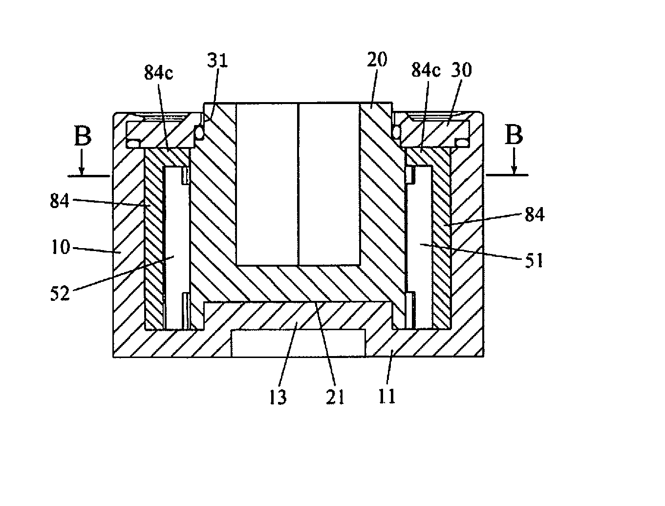
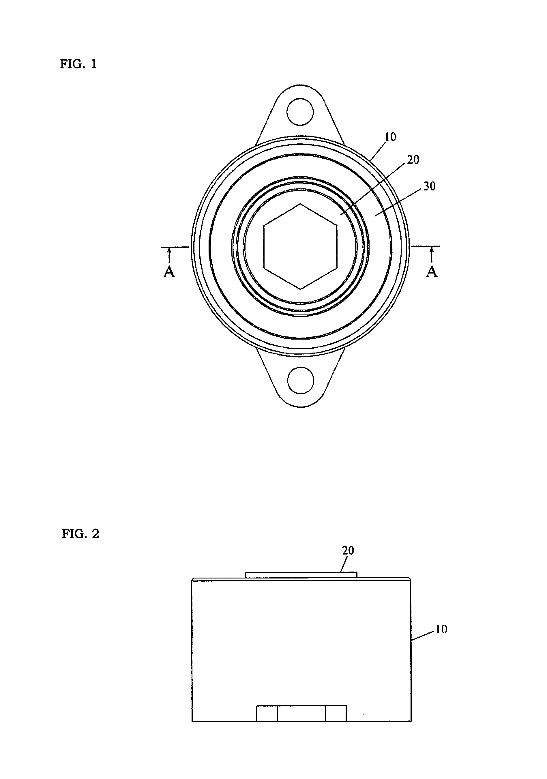
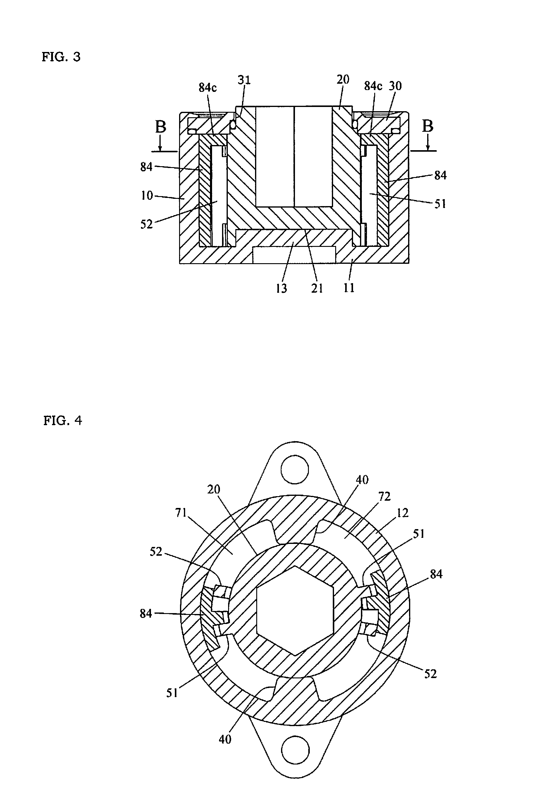
[0038]FIGS. 1 to 4 illustrate a rotary damper according to a first embodiment of the invention. As illustrated in these figures, the rotary damper according to the first embodiment includes a housing 10, a shaft 20, a plug 30, partitions 40, a viscous liquid and vanes.

[0039]The housing 10 is open at its one end, and is completely closed at the other end by an end wall 11 (see FIG. 3). The housing 10 has a cylindrical peripheral wall 12 integral with the end wall 11, and is hollow (see FIGS. 3 and 4). The end wall 11 has a bearing 13 (see FIG. 3). The end wall 11 completely closes the other end of the housing 10, and therefore an aperture extending through the end wall 11 cannot be employed as a bearing formed in the end wall 11. The bearing 13 in the first embodiment has a convex form, but may have a concave form.

[0040]The shaft 20 has a concavity fitted to the bearing 13 (see FIG. 3). When the bearing formed in the end wall 11 has a concave form, a shaft having a convexity fitted t...

second embodiment

[0047]A rotary damper according to the second embodiment differs from the rotary damper according to the first embodiment in structures of vanes and a valve body 84. More specifically, the vane of the second embodiment includes first and second pressurizing portions 51 and 52 similarly to the vanes of the first embodiment, but the first pressurizing portion 51 is axially longer than the second pressurizing portion 52 (see FIGS. 9 and 10). However, the axial length of the first pressurizing portion 51 is determined such that the first pressurizing portion 51 may not come into contact with a plug 30 during rotation of a housing 10 or a shaft 20.

[0048]Similarly to the valve body 84 of the first embodiment, the valve body 84 includes a stop 84c arranged between the plug 30 and the second pressurizing portion 52, but does not have a portion arranged between the plug 30 and the first pressurizing portion 51 (see FIGS. 9 and 10). FIG. 9 illustrates an arrangement of the valve body 84 in an...

third embodiment

[0052]A rotary damper according to the third embodiment differs in a structure of a valve body 84 from the rotary damper according to the first embodiment. The valve body 84 of the third embodiment further includes a stop 84d made of resin and arranged between an end wall 11 and vanes (first and second pressurizing portions 51 and 52) (see FIGS. 11 and 12).

[0053]An experiment was performed using the rotary damper according to the third embodiment and a rotary damper according to a comparative example. The rotary damper according to the comparative example does not have stops 84c and 84d, and is different in this structure from the rotary damper of the third embodiment.

[0054]In this experiment, a shaft was rotated by 60 degrees from an initial position in a braking force generating direction, and this rotation was repeated 30,000 times with a housing kept in a fixed state. A load applied to the shaft was 14 Nm, and plugs and vanes in both the third embodiment and the comparative exam...


PUM


Abstract

The present invention provides a rotary damper comprising a hollow housing (10) which is opened at its one end and completely closed at the other end by an end wall (11), a bearing (13) formed at the end wall (11), a shaft (20) fitted to the bearing (13), a plug (30) made of metal, having an aperture (31) supporting the shaft (20) and closing an opening in the housing (10), partitions (40) arranged inside the housing (10) for rotation in accordance with rotation of the housing (10), a viscous liquid filling chambers (71 and 72) defined by the partitions (40), and metal vanes (51 and 52) arranged in the chambers (71 and 72) for rotation in accordance with the rotation of the shaft (20), wherein the vane (51 and 52) includes a check valve, the check valve includes a valve body (84), and the valve body (84) includes a stop 84c made of resin and arranged between the plug (30) and the vanes (51 and 52).

Description

TECHNICAL FIELD[0001]The present invention relates to a rotary damper.BACKGROUND ART[0002]Conventionally, a rotary damper has been known that comprises a hollow housing which is opened at its one end and completely closed at the other end by an end wall, a bearing formed in the end wall, a shaft fitted to the bearing, a plug having an aperture supporting the shaft and closing an opening in the housing, a partition arranged inside the housing for rotation in accordance with rotation of the housing, a viscous liquid filling chambers defined by the partition, and a vane arranged in the chamber for rotation in accordance with the rotation of the shaft (see, e.g., JP 2008-082462 A).[0003]In this kind of the rotary damper, the end wall completely closes the other end of the housing. Therefore, when the housing or the shaft rotates, the viscous liquid flows into a space between the bearing and the shaft to float the shaft. Consequently, the vane slides in the state where it is pushed again...

Claims


Application Information

Patent Timeline
IPC IPC(8): F16F9/14
CPCF16F9/145
Inventor OZAKI, KEIGOKITADA, TATSUYA
Owner SOMIC MANAGEMENT HLDG INC
Why Eureka
Try Eureka