
Ultrasonic bonding systems and methods of using the same

Active Publication Date: 2014-02-20
ORTHODYNE ELECTRONICS
View PDF6 Cites 10 Cited by
  • Summary
  • Abstract
  • Description
  • Claims
  • Application Information

AI Technical Summary

Benefits of technology

The present invention provides an ultrasonic bonding system that includes a bond head assembly and a bonding tool, and a pressing member for independent press against a bonding material. This system can be used for bonding a ribbon material to a solar cell or a conductive material to a workpiece. The method involves applying ultrasonic energy to the bonding tool to form a bond, and then using the pressing member to maintain contact with the bond until it is no longer needed. The technical effects of this invention include improved bonding efficiency and accuracy, as well as simplified and automated production processes.

Problems solved by technology

In certain applications, problems have occurred related to the bonding tool sticking to the bonded ribbon.
If the bonding tool is stuck to (or otherwise bonded to) the ribbon material, during the lifting of the tool damage to the ribbon (or other portion of the solar substrate) may occur.
For example, ribbon material stuck to the tool may pull off from the substrate, and may further tear (or otherwise damage) adjacent portions of the surrounding substrate.

Method used


Image

  • Ultrasonic bonding systems and methods of using the same
  • Ultrasonic bonding systems and methods of using the same
  • Ultrasonic bonding systems and methods of using the same

Examples


Embodiment Construction

[0032]During ultrasonic bonding of a conductive material (e.g., a ribbon material) to a substrate, the ribbon is moved by a bonding tool relative to the underlying substrate to facilitate bond formation. Generally, relative motion between the bonding tool and the ribbon is undesirable. Such relative motion may cause the bonding tool to stick or become bonded to the ribbon based upon the same mechanism that bonds the ribbon to the substrate surface. If the bonding tool does stick to the ribbon during the bonding process, a portion of the ribbon (and perhaps a portion of the substrate under the ribbon and / or adjacent the ribbon) may lift up with the bonding tool (e.g., after the bonding is complete and the tool is raised), thereby damaging or even destroying the substrate. Such sticking problems may be worse during solar cell bonding (e.g., due to the mechanisms used to secure the solar substrate during bonding, for example, because of the geometry of the solar substrate). Such proble...


PUM

PropertyMeasurementUnit
Lengthaaaaaaaaaa
Electrical conductoraaaaaaaaaa

Abstract

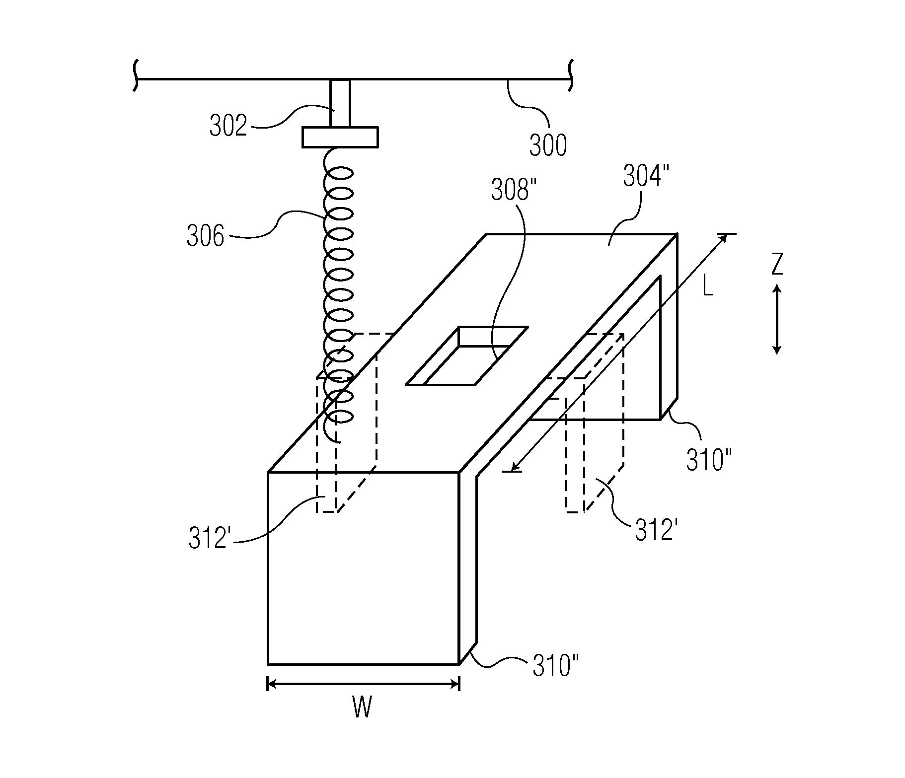
An ultrasonic bonding system is provided. The ultrasonic bonding system includes a bond head assembly and a bonding tool for bonding a conductive bonding material to a workpiece. The ultrasonic bonding system also includes a pressing member adapted to press against the workpiece, the pressing member being supported by the bond head assembly and being moveable with respect to the bond head assembly independent of the bonding tool. The pressing member includes a body portion and a plurality of pressing elements extending below the body portion, the pressing elements being configured to contact the workpiece.

Description

CROSS-REFERENCE TO RELATED APPLICATIONS[0001]This application is a continuation-in-part application of U.S. patent application Ser. No. 13 / 947,679 filed Jul. 22, 2013, which is a continuation of U.S. patent application Ser. No. 13 / 578,702 filed Aug. 13, 2012 (now U.S. Pat. No. 8,511,536), which claims the benefit of International Patent Application No. PCT / US2011 / 030537 filed Mar. 30, 2011, which claims the benefit of U.S. Provisional Application No. 61 / 319,605 filed on Mar. 31, 2010, the content of all of which is incorporated herein by reference.FIELD OF THE INVENTION[0002]The present invention relates to ultrasonic bonding operations, and more particularly, to wire and ribbon bonding systems for solar cells, semiconductor devices, and the like.BACKGROUND OF THE INVENTION[0003]In the processing and packaging of semiconductor devices, ultrasonic bonding (e.g., wire bonding, ribbon bonding, etc.) continues to be a widely used method of providing electrical interconnection between tw...

Claims


Application Information

Patent Timeline
IPC IPC(8): B23K20/00B23K20/10
CPCB23K20/10B23K20/004H01L2224/78343H01L24/45H01L24/78H01L24/84H01L24/85H01L31/188H01L2224/45014H01L2224/85205H01L2924/01005H01L2924/01006H01L2924/01013H01L2924/01014H01L2924/01023H01L2924/01029H01L2924/01033H01L2924/01047H01L2924/01074H01L2924/01082H01L2924/014H01L2924/00014H01L2224/77343H01L2224/84205H01L24/37H01L24/77H01L2224/37124H01L2224/37147H01L2224/78313H01L2224/78315H01L2224/78316H01L2224/78611H01L2224/8512H01L2224/37139H01L2224/773H01L2224/77313H01L2224/77315H01L2224/77316H01L2224/77321H01L2224/77352H01L2224/77611H01L2224/77702H01L2224/783H01L2224/78321H01L2224/78352H01L2224/78702H01L2224/8412H01L2224/45099H01L2924/01026H01L2924/04563H01L2924/00012H01L2924/206H01L2224/73221Y02E10/50
Inventor LUECHINGER, CHRISTOPH B.VALENTIN, ORLANDO L.XU, TAO
Owner ORTHODYNE ELECTRONICS
Learn More