Vibration isolation systems

Inactive Publication Date: 2014-02-20
MINUS K TECH
View PDF11 Cites 25 Cited by
  • Summary
  • Abstract
  • Description
  • Claims
  • Application Information

AI Technical Summary

Benefits of technology

[0008]The present invention represents improvements over my previous isolation systems utilizing isolators with negative-stiffness mechanisms to produce low vertical and horizontal natural frequencies by allowing both the horizontal stiffness and horizontal natural frequencies to be adjusted, for example, by turning adjustment screws. In my previous isolators, only the vertical stiffness and vert

Problems solved by technology

There are, however, shortcomings and disadvantages associated with these particular prior art isolation systems which prevent them from obtaining low system natural frequencies and from limiting resonant responses to low values while providing high isolation performance at the higher frequencies.
This loading to approach the point o

Method used


Image

  • Vibration isolation systems
  • Vibration isolation systems
  • Vibration isolation systems

Examples


Example

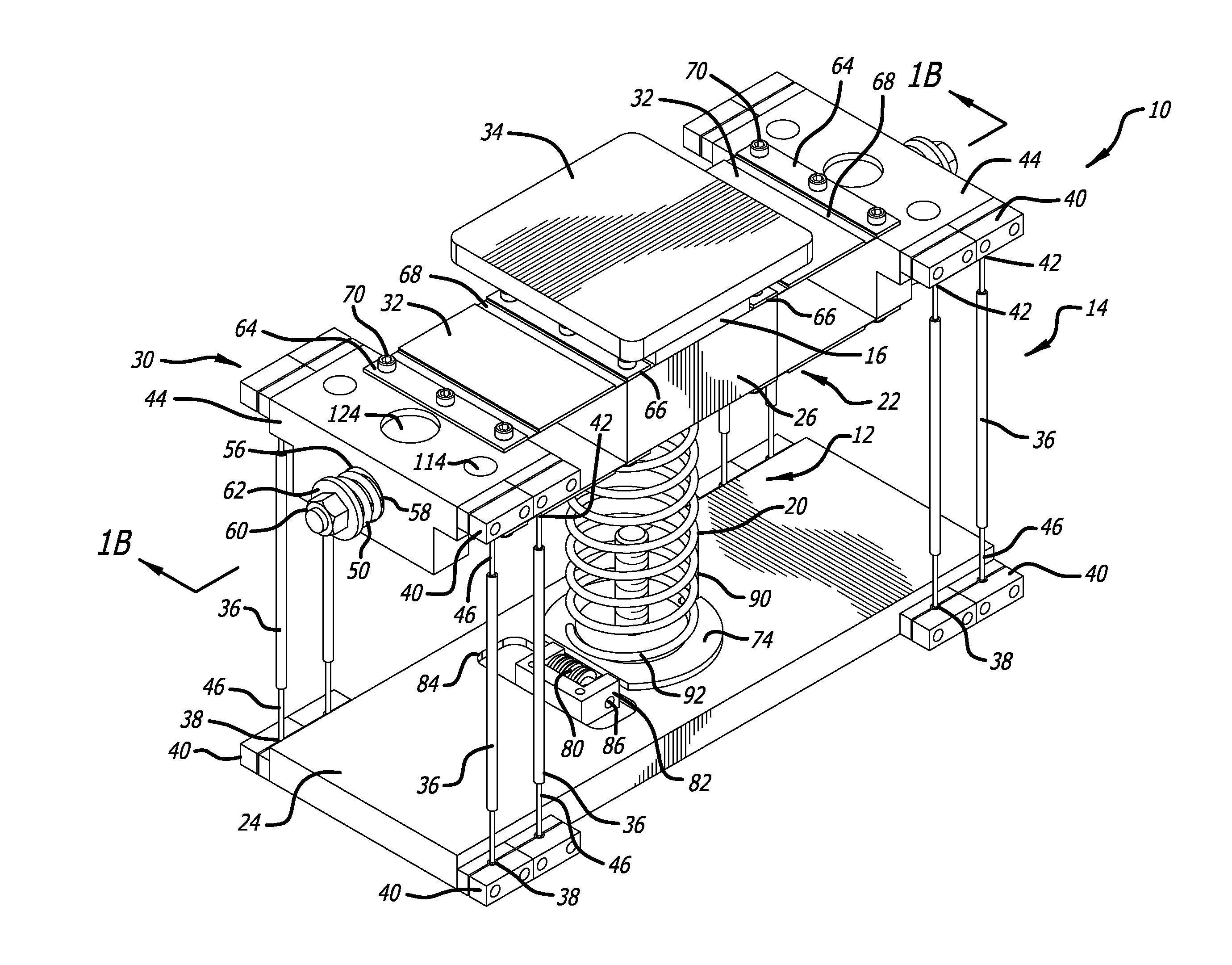
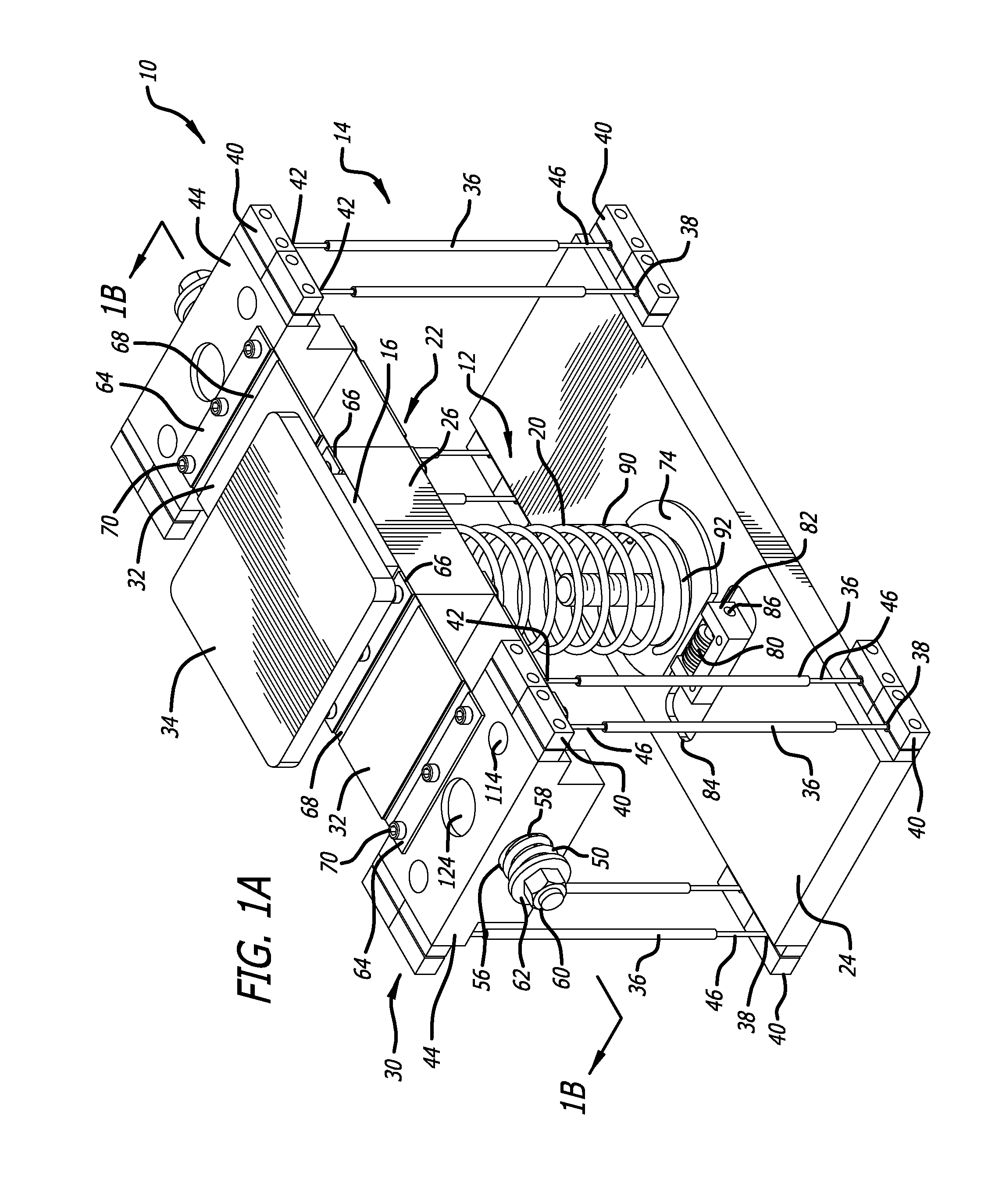
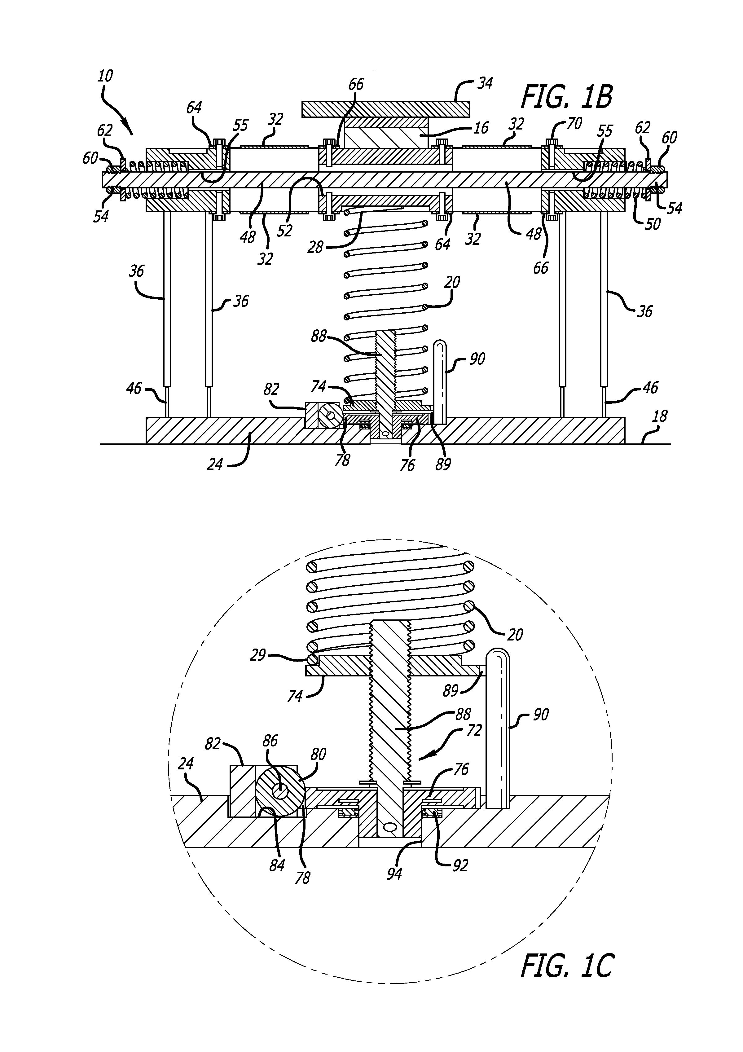
[0026]As is shown in the drawings for purposes of illustration, the present invention is embodied in a vibration-isolating suspension system comprising a payload platform supported on a vertical-motion, horizontal-motion and tilt-motion isolator. The improvements of the present invention are found in several embodiments of a composite isolator as shown in FIGS. 1A-9. As the present invention is described in detail as applied to the particular isolators shown in these figures, those skilled in the art will appreciate that these improvements can also be used in conjunction with other isolators as well.

[0027]FIGS. 1A-3 show one embodiment of a vibration isolation system 10 made in accordance with the present invention. The system utilizes a vertical-motion isolator 12, a horizontal-motion isolator 14 and a tilt-motion isolator 16. The embodiment of the isolator system 10 of FIGS. 1A-3 is designed to support a payload (not shown) relative to a foundation 18 to reduce the transmission of...


PUM


Abstract

A composite vibration isolation system utilizes isolators with negative-stiffness mechanisms to produce low vertical and horizontal natural frequencies to the system by allowing both the horizontal stiffness and horizontal natural frequencies to be adjusted, for example, by turning adjustment screws.

Description

BACKGROUND OF THE INVENTION[0001]This invention relates generally to suspension systems for isolating and reducing the transmission of vibratory motion between an object or payload and a base and, more particularly, to an omnidirectional suspension or vibration-isolating system which exhibits low stiffness both vertically in the direction of the weight load and horizontally in directions transverse to the weight load to effectively reduce the transmission of vibrations between the object and the base. The present invention represents improvements over my previous isolators which utilize negative-stiffness mechanisms to produce low vertical and horizontal natural frequencies and which rely on a principle of loading a particular elastic structure which forms the isolator or a portion of it to approach the elastic structure's point of elastic instability.[0002]The problems caused by unwanted vibration on equipment, devices and processes that are extremely motion sensitive have been wid...

Claims


Application Information

Patent Timeline
IPC IPC(8): F16F15/02
CPCF16F15/04F16F2228/063
Inventor PLATUS, DAVID L.
Owner MINUS K TECH
Why Eureka
Try Eureka