Zoom lens and image pickup apparatus including the same

a technology which is applied in the field of zoom lens and image pickup apparatus, can solve the problems of increasing the size of the entire lens system, the change of angle of field accompanying focus adjustment, and the increase of the number of lenses, so as to reduce breathing, reduce the effect of focusing and focusing

Active Publication Date: 2014-02-20
CANON KK
View PDF1 Cites 12 Cited by
  • Summary
  • Abstract
  • Description
  • Claims
  • Application Information

AI Technical Summary

Benefits of technology

[0013]In view of the above, the present invention provides a zoom lens in which, by appropriately setting configurations, refractive powers, and the like of a first lens unit and sub lens units which move for focusing as sub systems thereof, aberration variations during focusing, which are conspicuous at a telephoto end, are suppressed while suppressing breathing, which is conspicuous especially at a wide angle end. Further, the present invention provides a zoom lens having a large aperture ratio, a high zoom ratio, a small size, and high performance, with an F-number at the wide angle end of about 1.8 to 2.7, an angle of field at the wide angle end of about 50 to 70 degrees, an angle of field at the telephoto end of about 1 to 8 degrees, and a zoom ratio of about 7 to 70.

Problems solved by technology

On the other hand, a lens generally has a problem in that the angle of field changes accompanying focus adjustment (hereinafter referred to as breathing).
In general, in order to attain a zoom lens having a large aperture ratio and a high zoom ratio in which aberration variations are small and optical performance is high over an entire zoom range and an entire focus range, and in which the breathing is little at the wide angle end, there occurs a problem in that the number of lenses is increased, which leads to an increase in size of the entire lens system.
Further, in order to attain a zoom lens having high optical performance in which the aberration variations are small over the entire focus range at the telephoto end, there occurs a problem in that the number of lenses of the first lens unit is further increased, which leads to an increase in size of the entire lens system.
H09-258102, it is difficult to attain both the high optical performance and the suppression of the breathing at the wide angle end in the zoom lens having an angle of field at the telephoto end of less than 10 degrees.

Method used


Image

  • Zoom lens and image pickup apparatus including the same
  • Zoom lens and image pickup apparatus including the same
  • Zoom lens and image pickup apparatus including the same

Examples


embodiment 1

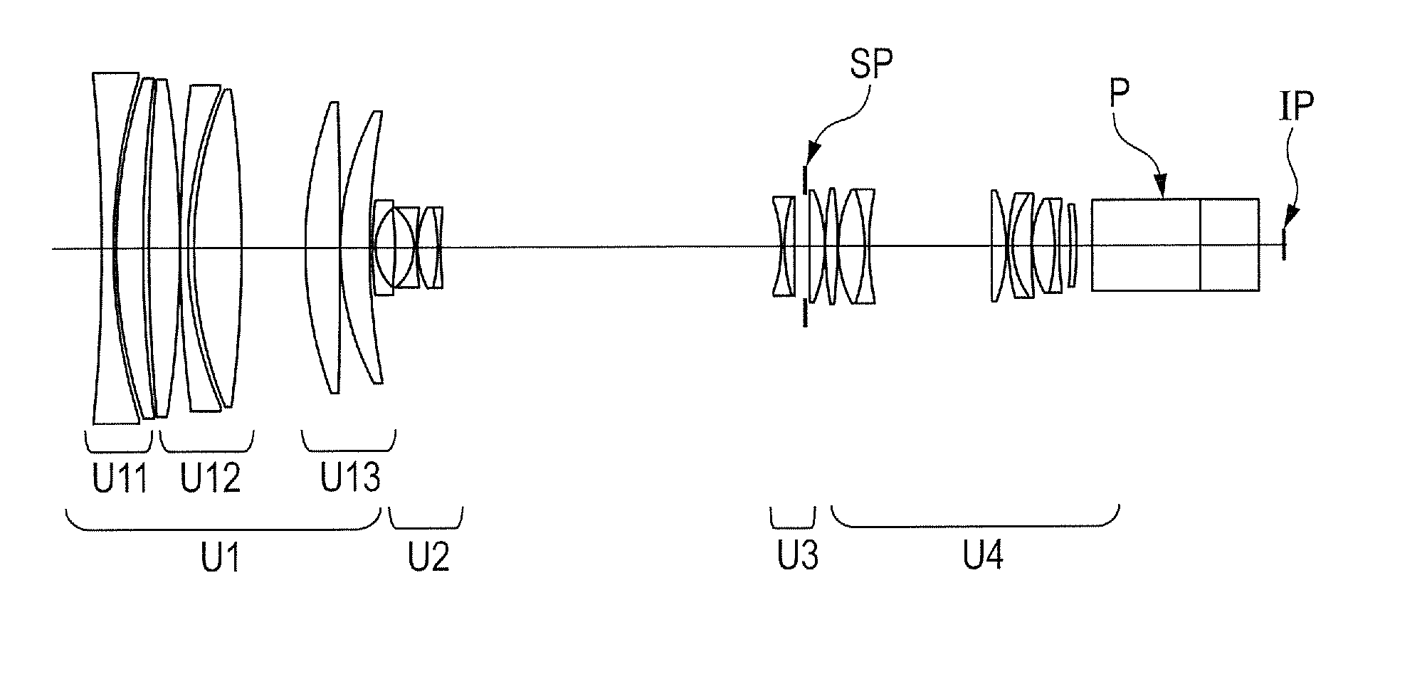
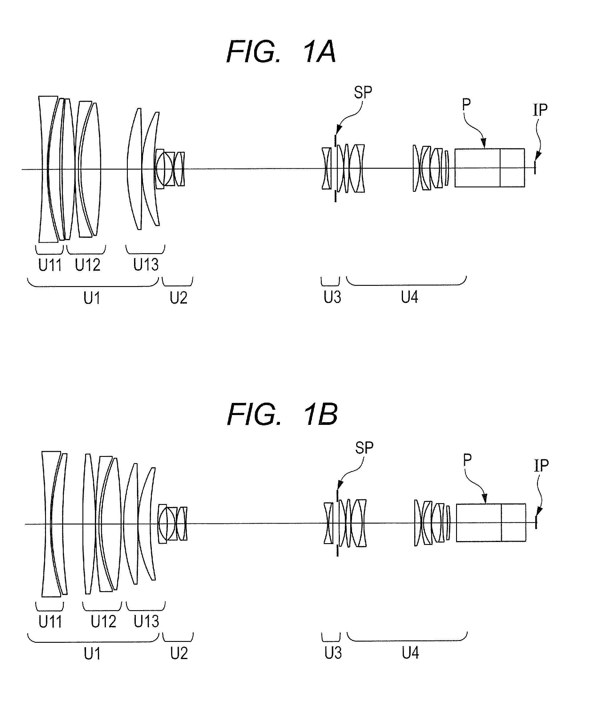
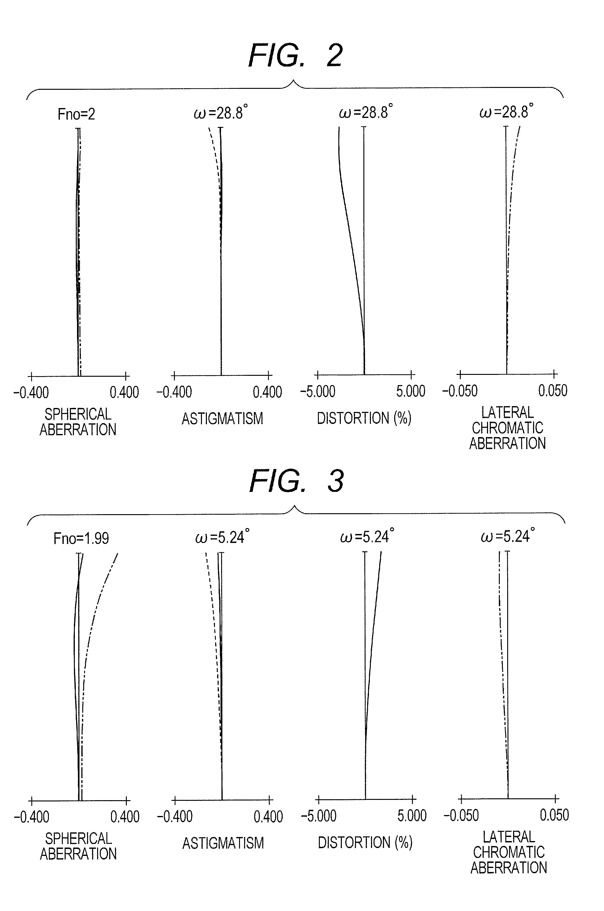
[0084]FIGS. 1A and 1B illustrate the zoom lens according to Embodiment 1 (Numerical Embodiment 1) of the present invention, of which FIG. 1A is a lens cross-sectional view when focused on the object at infinity at a wide angle end, and FIG. 1B is a lens cross-sectional view when focused on the object at the minimum distance (2.5 m) at the wide angle end. FIG. 2 is a longitudinal aberration diagram when focused on the object at infinity at the wide angle end according to Numerical Embodiment 1. FIG. 3 is a longitudinal aberration diagram when focused on the object at infinity at a focal length of 60 mm according to Numerical Embodiment 1. FIGS. 4A, 4B, and 4C are longitudinal aberration diagrams at a telephoto end according to Numerical Embodiment 1, of which FIG. 4A is a longitudinal aberration diagram when focused on the object at infinity, FIG. 4B is a longitudinal aberration diagram when focused on an object distance of 7 m, and FIG. 4C is a longitudinal aberration diagram when f...

embodiment 2

[0091]FIGS. 6A and 6B illustrate a zoom lens according to Embodiment 2 (Numerical Embodiment 2) of the present invention, of which FIG. 6A is a lens cross-sectional view when focused on the object at infinity at a wide angle end, and FIG. 6B is a lens cross-sectional view when focused on the object at the minimum distance (0.82 m) at the wide angle end. FIG. 7 is a longitudinal aberration diagram when focused on the object at infinity at the wide angle end according to Numerical Embodiment 2. FIG. 8 is a longitudinal aberration diagram when focused on the object at infinity at a focal length of 41 mm according to Numerical Embodiment 2. FIGS. 9A, 9B, and 9C are longitudinal aberration diagrams at the telephoto end according to Numerical Embodiment 2, of which FIG. 9A is a longitudinal aberration diagram when focused on the object at infinity, FIG. 9B is a longitudinal aberration diagram when focused on an object distance of 2.5 m, and FIG. 9C is a longitudinal aberration diagram whe...

embodiment 3

[0095]FIGS. 11A and 11B illustrate a zoom lens according to Embodiment 3 (Numerical Embodiment 3) of the present invention, of which FIG. 11A is a lens cross-sectional view when focused on the object at infinity at a wide angle end, and FIG. 11B is a lens cross-sectional view when focused on the object at the minimum distance (3.5 m) at the wide angle end. FIG. 12 is a longitudinal aberration diagram when focused on the object at infinity at the wide angle end according to Numerical Embodiment 3. FIG. 13 is a longitudinal aberration diagram when focused on the object at infinity at a focal length of 70 mm according to Numerical Embodiment 3. FIGS. 14A, 14B, and 14C are longitudinal aberration diagrams at the telephoto end according to Numerical Embodiment 3, of which FIG. 14A is a longitudinal aberration diagram when focused on the object at infinity, FIG. 14B is a longitudinal aberration diagram when focused on an object distance of 7 m, and FIG. 14C is a longitudinal aberration di...


PUM


Abstract

A zoom lens in which aberration variations at telephoto end during focusing are suppressed while suppressing breathing at wide angle end, which includes, from object side: a positive first unit which does not move for zooming; a negative second unit which moves during zooming; at least one zooming unit which moves during zooming; a stop; and an imaging unit which does not move for zooming. The first unit includes: a negative first sub unit which does not move for focusing; a positive second sub unit which moves to image side during focusing from infinity to proximity; and a positive third sub unit which moves to object side during focusing from infinity to proximity. Focal lengths of the first, second, first sub, and second sub units, and amounts of movement of the second and third sub units during the focusing from infinity proximity are appropriately set.

Description

BACKGROUND OF THE INVENTION[0001]1. Field of the Invention[0002]The present invention relates to a zoom lens and an image pickup apparatus including the zoom lens which is suitable for use in a broadcasting television camera, a cinema camera, a video camera, a digital still camera, and a silver-halide film camera, for example.[0003]2. Description of the Related Art[0004]In recent years, a zoom lens having a large aperture ratio, a high zoom ratio, and high optical performance is required for an image pickup apparatus such as a television camera, a cinema camera, a film camera, or a video camera. In particular, in the television / cinema camera as a professional video photography system, image pickup devices having image sizes of a wide range from ½ inch (diagonal length: 8 mm) and ⅔ inches (diagonal length: 11 mm) to 35 mm (diagonal length: about 28 to 43.3 mm) have been introduced in the market. Mainstream image pickup devices such as a charge coupled device (CCD) and a complementary...

Claims


Application Information

Patent Timeline
Patent Type & Authority Applications(United States)
IPC IPC(8): G02B15/14
CPCG02B15/14G02B15/17G02B15/144109
Inventor SHIMOMURA, KAZUYA
Owner CANON KK
Why Eureka
Try Eureka