

Determining propagation delay of communications in distributed antenna systems, and related components, systems, and methods
a technology of distributed antennas and delay, applied in the direction of transmission monitoring, synchronisation arrangement, wireless communication, etc., can solve the problems of increasing delay, poor wireless reception, and affecting other services, so as to improve efficiency, efficiency, and/or accuracy of delay based operations
- Summary
- Abstract
- Description
- Claims
- Application Information
AI Technical Summary
Benefits of technology
Problems solved by technology
Method used
Image

Examples
Embodiment Construction
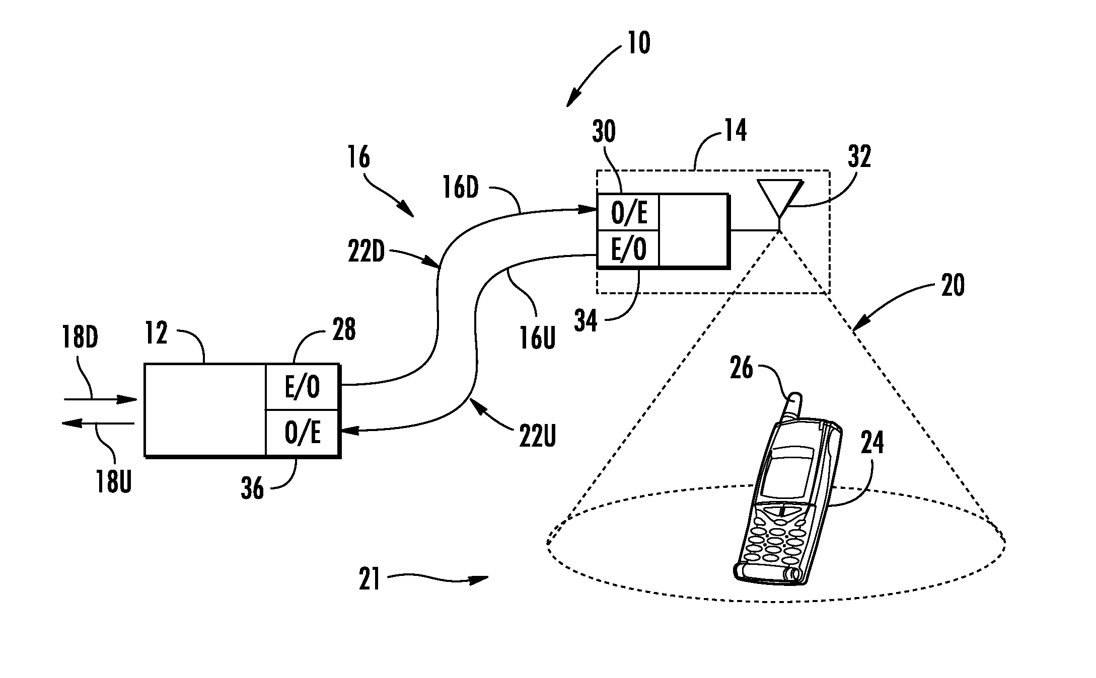
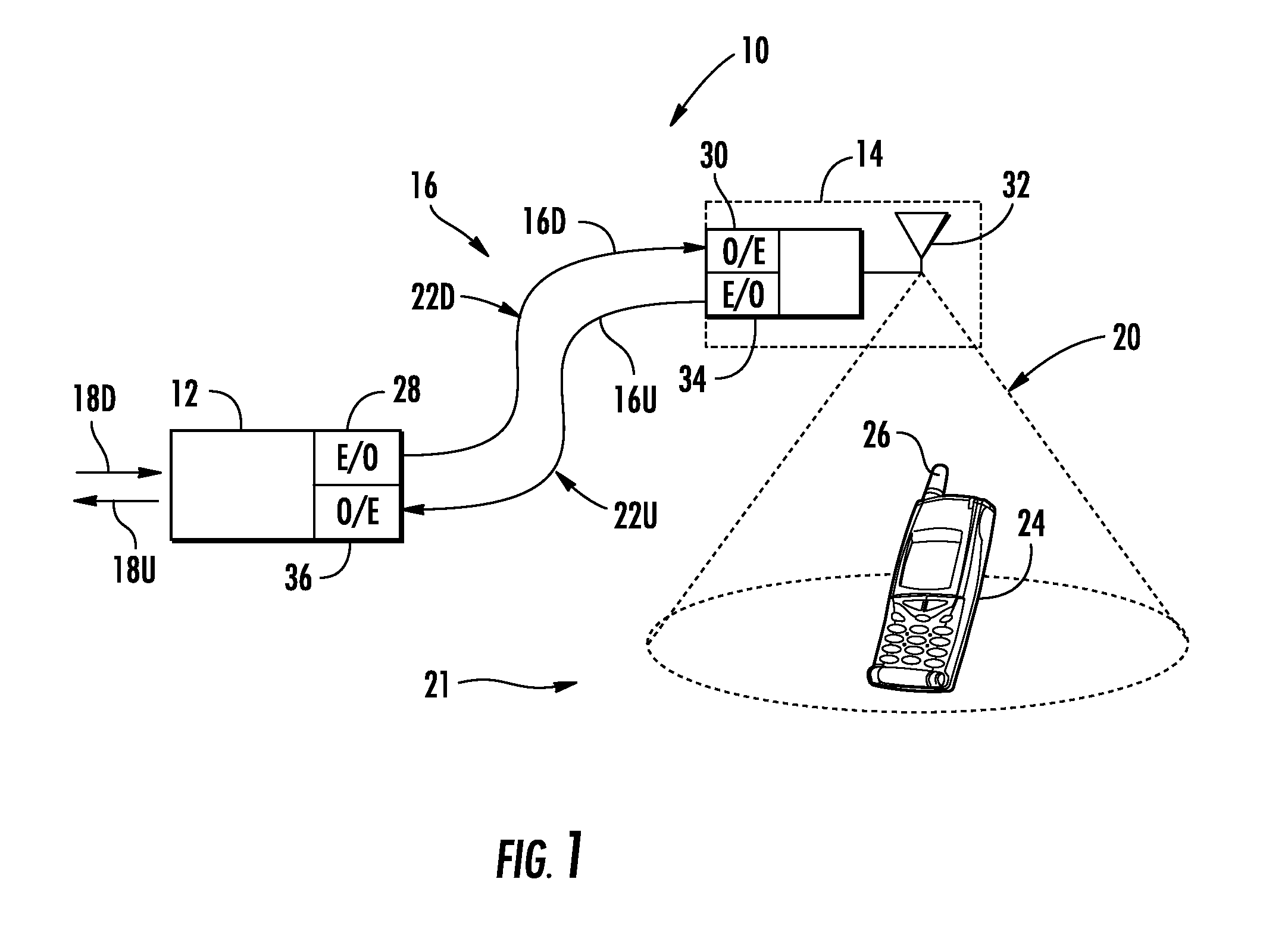
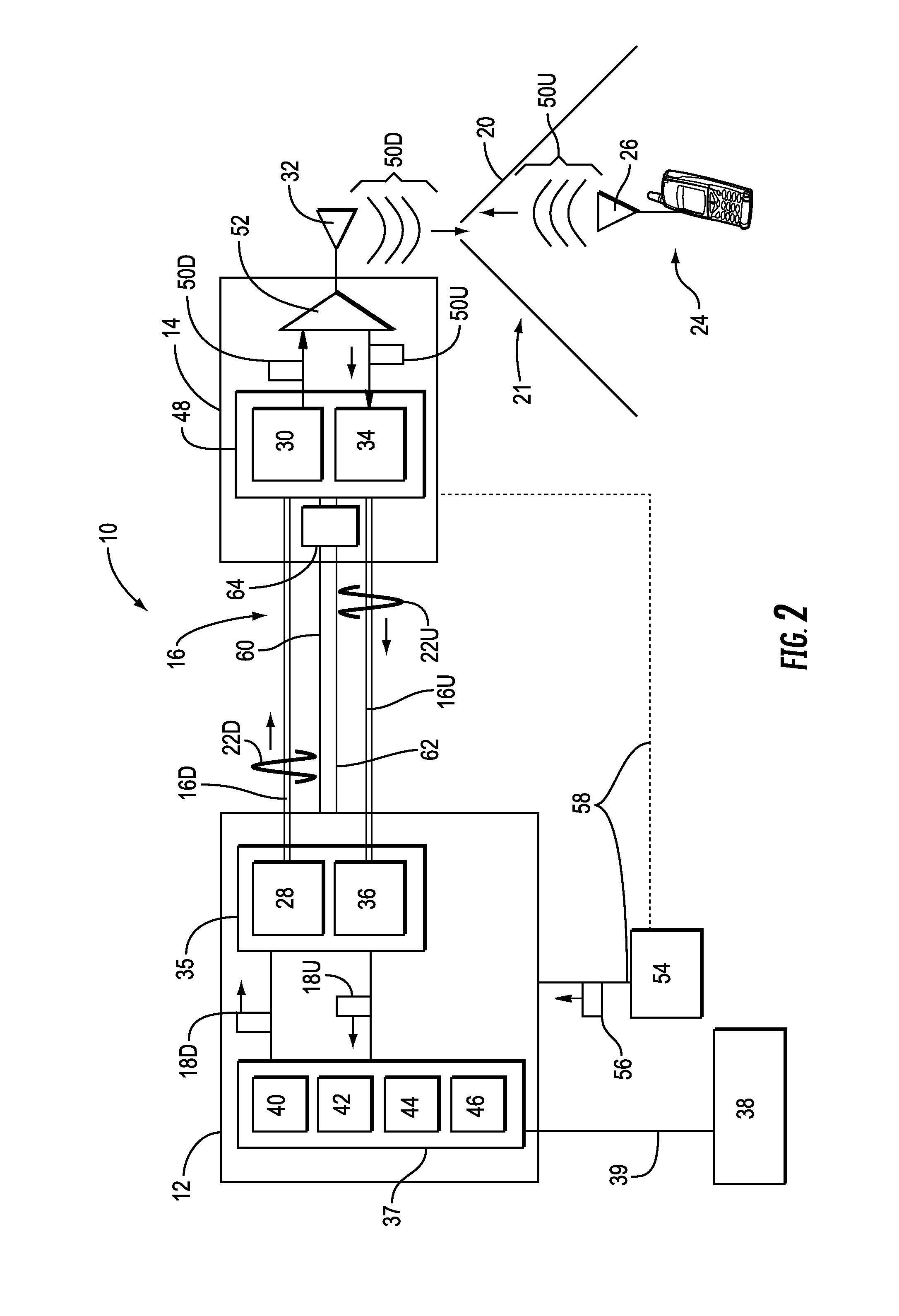
[0012]Embodiments disclosed in the detailed description include components, systems, and methods for determining propagation delay of communications in distributed antenna systems. The propagation delay of communications signals distributed in the distributed antenna systems is determined If desired, the propagation delay(s) can be determined on a per remote antenna unit basis for the distributed antenna systems. The propagation delay(s) can be provided by the distributed antenna systems to a network or other system to be taken into consideration for communications services or operations that are based on communications signal delay. Delay based operations may be made more effective, efficient, and / or accurate by knowing the propagation delay experienced in a distributed antenna system.
[0013]As a non-limiting example, the determined propagation delay(s) can be to be taken into consideration for communications services or operations that are based on communications signal delay. As a...
PUM
 Abstract
Description
Claims
Application Information