Apparatus and Methods for Limiting or Preventing Backflow of Gas up Through a Plumbing Fixture

a technology of plumbing fixtures and apparatus, which is applied in the direction of mechanical equipment, transportation and packaging, and functional valve types, etc., can solve the problems of foul smelling and sometimes harmful gasses in the piping below the plumbing fixture, backflow of gas from underneath the plumbing fixture, and ineffective p-traps to block the backflow of gas

Inactive Publication Date: 2014-02-27
RECTORSEAL
View PDF9 Cites 26 Cited by
  • Summary
  • Abstract
  • Description
  • Claims
  • Application Information

AI Technical Summary

Benefits of technology

[0011]The disc has a central axis and is pivotably connected to the frame between the first and second sides of the interior surface thereof. The disc is pivotably movable between a closed position and at least one open position within the central passageway about its central axis. The disc has a first section configured to engage the downwardly facing ledge of the interior surface of the frame and a second section configured to simultaneously engage the upwardly facing ledge. The disc is configured so that the engagement of the first section with the downwardly facing ledge and the second section with the upwardly facing ledge stops the pivoting movement of the disc in one direction and defines the closed position of the disc relative to the frame. The closed position of the disc limits or prevents fluid communication between the drain basin and the destination through the central passageway. When the first and second sections are simultaneously disengaged from the respective downwardly and upwardly facing ledges, the disc is in an open position and allows fluid communication between the drain basin and the destination through the central passageway.
[0012]In various embodiments, the present disclosure involves a valve useful for allowing the flow of liquid down through a pluming fixture to a destination below it and limiting or preventing the backflow of gas from the destination up into the pluming fixture. The valve includes a circular-shaped frame and a rigid disc. The frame is configured to be positioned between the plumbing fixture and destination, and includes a central passageway in fluid communication with the plumbing fixture and the destination. The disc includes upper and lower surfaces and is pivotably connected to the frame within the central passageway.
[0013]The disc is pivotably movable between a closed position and at least one open position. The closed position limits or prevents, and the open position allows, fluid communication between the plumbing fixture and the destination through the central passageway. The disc is biased in the closed position sufficient to prevent the forces of backflow gas from the destination acting upon the lower surface of the rigid disc from moving the rigid disc into an open position. The disc is automatically moveable from the closed position into the open position upon the application of sufficient forces on the upper surface thereof caused by fluid in the central passageway, and thereafter automatically moveable from the open position to the closed position upon the absence of sufficient fluid in the central passageway to overcome the biasing forces acting upon the disc.

Problems solved by technology

One well-known problem with plumbing fixtures is the backflow of gas from underneath the plumbing fixture.
As is well known, foul-smelling and sometimes harmful gasses exist in the piping below the plumbing fixture, sewage system or other destination.
In some circumstances, the P-traps are not always effective at blocking the backflow of gas.
However, trap primers are often difficult and expensive to install and may require maintenance and frequent monitoring.
Various problems may exist with these types of valves.
For example, these valves may be prone to clogging or freeze-up due to the presence or build-up of debris or substances such as grease, wax, dirt, sand, and other organic and inorganic materials.
These solutions are typically complicated, expensive, may require maintenance and tight tolerances to work effectively, and may be prone to clogging or freeze-up due to the presence or build-up of debris or substances (e.g. grease, wax, dirt, sand and other organic and inorganic materials).

Method used


Image

  • Apparatus and Methods for Limiting or Preventing Backflow of Gas up Through a Plumbing Fixture
  • Apparatus and Methods for Limiting or Preventing Backflow of Gas up Through a Plumbing Fixture
  • Apparatus and Methods for Limiting or Preventing Backflow of Gas up Through a Plumbing Fixture

Examples


Embodiment Construction

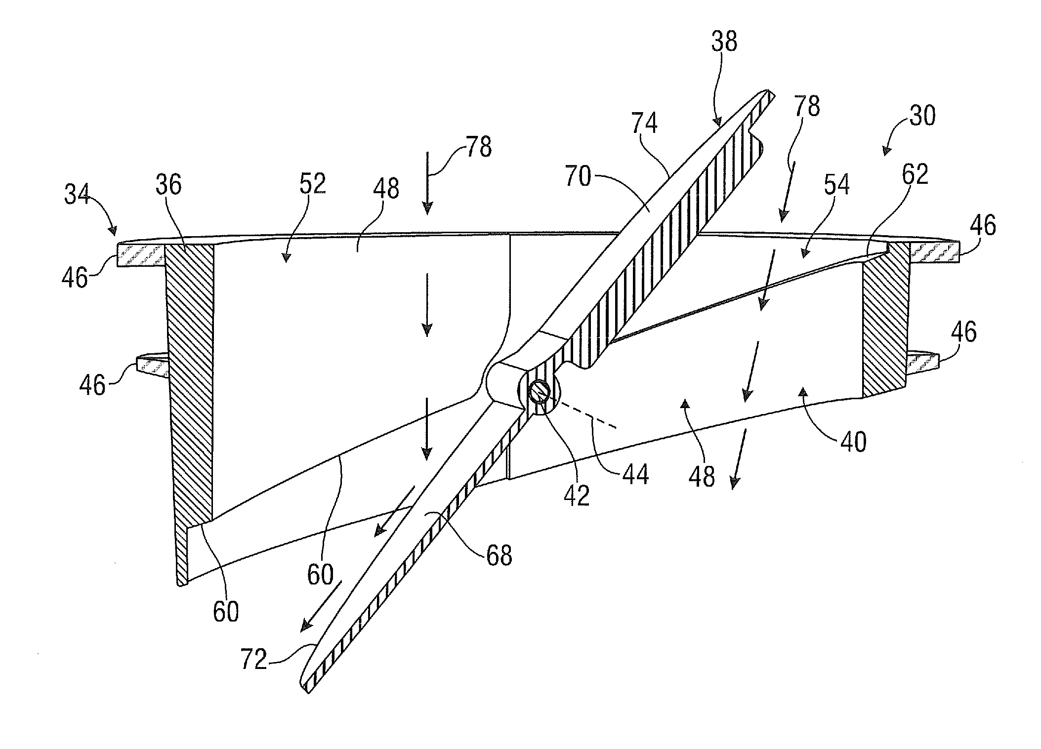
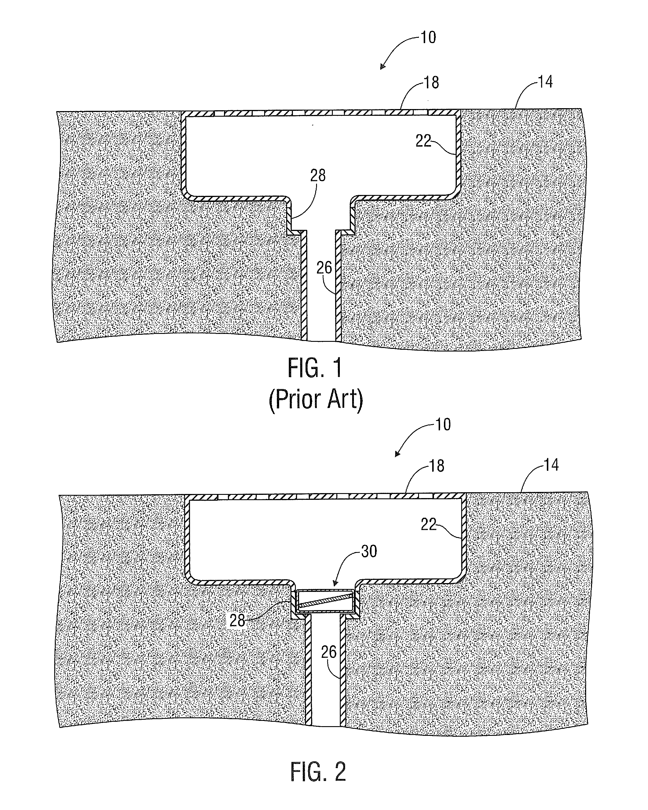
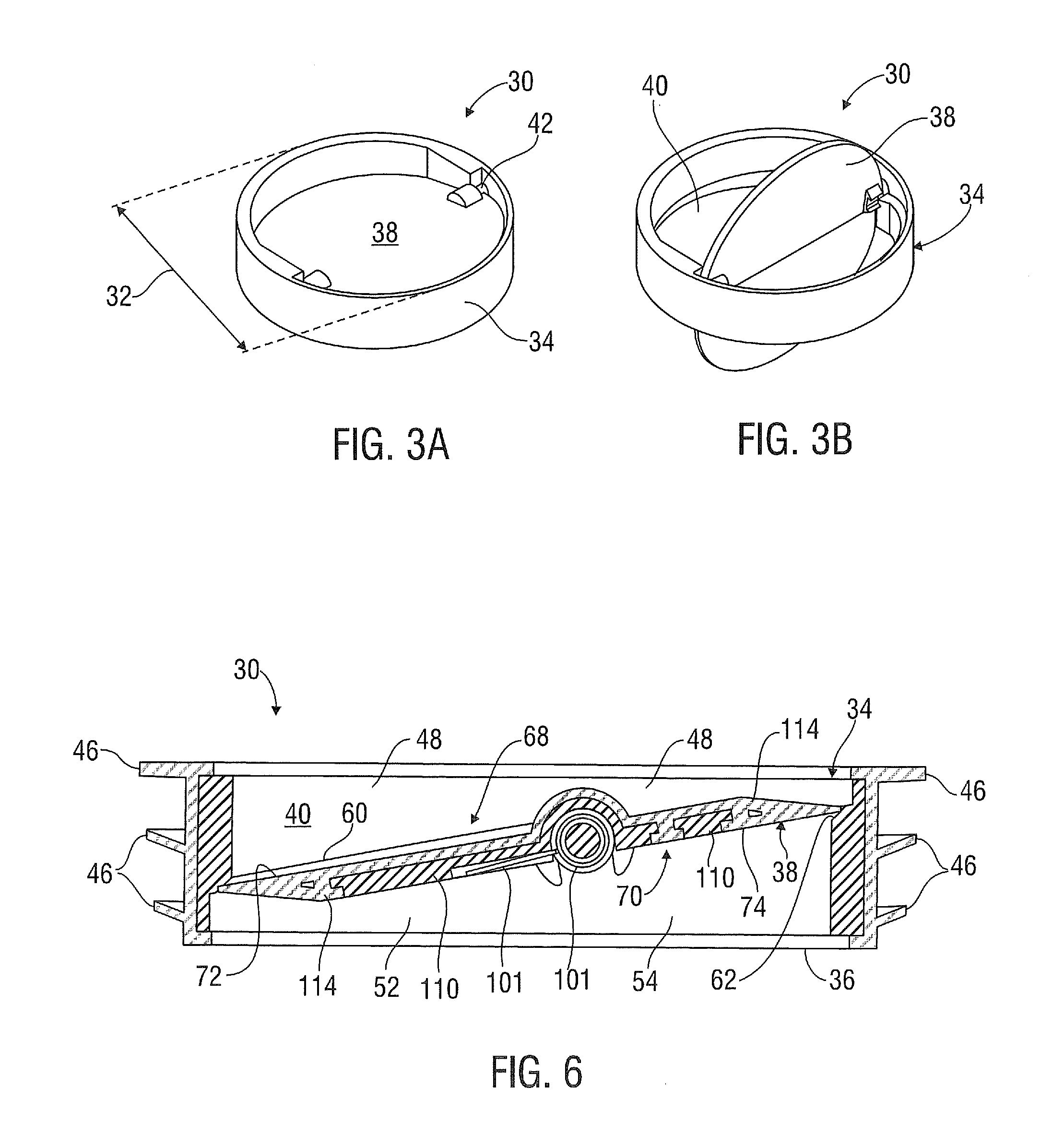
[0023]Characteristics and advantages of the present disclosure and additional features and benefits will be readily apparent to those skilled in the art upon consideration of the following detailed description of exemplary embodiments and referring to the accompanying figures. It should be understood that the description herein and appended drawings, being of example embodiments, are not intended to limit the claims of this patent or any patent or patent application claiming priority hereto. On the contrary, the intention is to cover all modifications, equivalents and alternatives falling within the spirit and scope of the claims. Many changes may be made to the particular embodiments and details disclosed herein without departing from such spirit and scope.

[0024]In showing and describing preferred embodiments, common or similar elements are referenced with like or identical reference numerals or are apparent from the appended figures and / or the description herein. When multiple fig...


PUM


Abstract

Apparatus useful for allowing the flow of liquid down through a pluming fixture to a destination below it and limiting or preventing the backflow of gas from the destination up into the pluming fixture includes a frame and a disc pivotably connected thereto. The disc is biased in a closed position and pivotably moveable into an open position upon the application of sufficient forces acting on the upper surface thereof caused by fluid from the plumbing fixture.

Description

CROSS REFERENCE TO RELATED APPLICATIONS[0001]This application claims priority to U.S. Provisional Patent Application Ser. Nos. 61 / 743,149 filed on Aug. 27, 2012 and entitled “Waterless Drain Trap Seal Protection Device” and 61 / 957,207 filed on Jun. 26, 2013 and entitled “Waterless Drain Trap Seal Protection Device”, the entire contents of which are hereby incorporated by reference herein in their entireties.FIELD OF THE INVENTION[0002]The present disclosure relates generally to plumbing methods and apparatus, and more particularly, apparatus and methods for limiting or preventing the backflow of gas through plumbing fixtures.BACKGROUND OF THE INVENTION[0003]One well-known problem with plumbing fixtures is the backflow of gas from underneath the plumbing fixture. For example, the plumbing fixture may be a floor-mounted drain system that leads to a sewage system. As shown in FIG. 1, a conventional floor-mounted drain system 10 is typically installed in a floor 14 (e.g. concrete, aspha...

Claims


Application Information

Patent Timeline
Patent Type & Authority Applications(United States)
IPC IPC(8): F16K15/03E03C1/298
CPCE03C1/298F16K15/03F16K15/033E03F2005/0417Y10T137/7903
Inventor MARTINELLI, ROBERT ALLENXU, ZHENG-YIROY, TONMOY
Owner RECTORSEAL
Why Eureka
Try Eureka