Tubelamp retrofit pin safety implementation using existing ballast and fixture

Active Publication Date: 2014-02-27
KONINKLIJKE PHILIPS ELECTRONICS NV
View PDF5 Cites 69 Cited by
  • Summary
  • Abstract
  • Description
  • Claims
  • Application Information

AI Technical Summary

Benefits of technology

[0007]It is possible to configure automatic switches that react only to voltages above a predefined threshold level, such as a voltage of the same order as a mains voltage for which the lamp is intended. This further increases the safety of the device. An automatic switch is preferably adapted to open the electric circuit when the voltage at the concerned pair of connection pins decreases to zero and may do so by interrupting the connection between a connection pin and a terminal. Similarly, the automatic switch may also be adapted to open the circuit when the voltage goes below a predefined voltage. Suitably, the automatic switch reacts to a voltage drop in short time. The automatic switch may react as fast as a normal residual current circuit breaker does, that is, the non-inserted pair

Problems solved by technology

Depending on the internal circuitry of the lamp, potentially hazardous conditions may arise when the lamp is partially inserte

Method used


Image

  • Tubelamp retrofit pin safety implementation using existing ballast and fixture
  • Tubelamp retrofit pin safety implementation using existing ballast and fixture
  • Tubelamp retrofit pin safety implementation using existing ballast and fixture

Examples


first embodiment

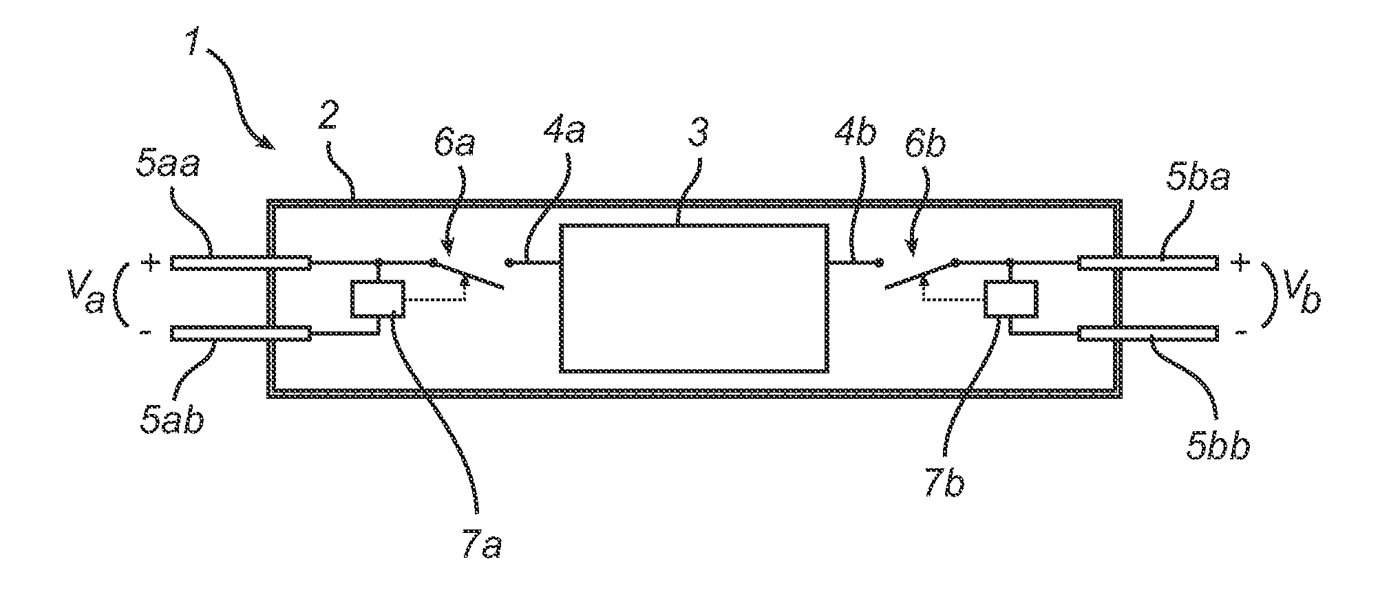
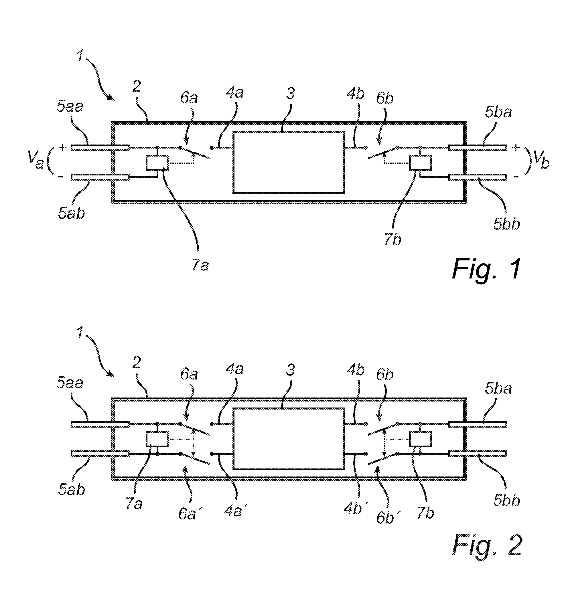
[0024]FIG. 1 shows the invention as an electric lamp 1, with a cylindrical shape, particularly a tubular shape. Externally, the lamp 1 comprises a light-transparent and electrically isolating housing 2, through which two connection pins 5 extend on each side. By being embedded in the material of the housing 2, the pins 5 on each side maintain a fixed spacing and relative orientation, and may therefore be said to form a pair. The pair of pins 5 on each side are adapted to be received by an electric socket. A lighting module 3, which is responsible for generating the light to be emitted by the lamp, is arranged inside the housing and comprises two terminals 4. The lighting module 3 may be an LED module for instance for enabling the electric lamp 1 to retrofit a conventional fluorescent lamp, like a TL lamp. Said LED module 3 may comprise an inorganic LED, a plurality of LEDs, an OLED or another type of solid state light source. The lighting module can also be embodied as an incandesce...

second embodiment

[0025]FIG. 2 shows a second embodiment, which differs from the lamp of FIG. 1 mainly with respect to the number of terminals 4 of the lighting module 3 and accordingly, with respect to the number of automatic switches 6 provided to connect these to corresponding external connection pins 5. More precisely, the lighting module 3 comprises four terminals 4, which may be connected within the module 3 by a broad range of possible electric networks. On the outside, the present embodiment achieves a non-permanent electric connection of each terminal 4 to a respective connection pin 5 and further, when the pins are inserted into a corresponding socket, to a respective socket terminals within the socket (not shown). Hence, the lighting module 3 may be powered either between two terminals 4 located on opposite sides, or between two terminals 4 on the same side, or by a combination of these. The terminals 4 not used for powering may supply the lighting module 3 with one or more control signals...


PUM


Abstract

An electric lamp (1) has two pairs of external connection pins (5) adapted for connecting the lamp to a voltage source for powering an internal lighting module (3). Each pair of pins is disconnected from the lighting module by an open switch (6) unless a non-zero electric voltage is applied to the pair and causes the switch to close. The lamp is therefore safe to handle even in a condition where one pair of pins is connected and the other is not. The lamp may be fitted in a switch-start fixture, providing an ohmic connection between two pins in different pairs, as well as a rapid-start fixture, with a capacitive connection.

Description

FIELD OF THE INVENTION[0001]The present invention generally relates to safety arrangements in electric retrofit devices. More precisely, it relates to a tube lamp retrofit with arrangements for preventing the occurrence of a harmful voltage at its external connection pins.BACKGROUND OF THE INVENTION[0002]Conventional tube lamps (fluorescent lamps) of the type having a two-pin connector at each end of the tube are, in steady-state operation, powered by a DC or AC electric current flowing between the connectors. The connectors are electrically disconnected until an arc has established in the tube. For this purpose, a starting procedure including preheating of the electrodes may be carried out by dedicated starting circuitry, which can be made inherently safe by being enabled only when the lamp is properly inserted into the fixture, so that live electric parts are always protected from touch. The starting circuitry may be of the switch-start / preheat, rapid-start or other type, and is c...

Claims


Application Information

Patent Timeline
IPC IPC(8): F21V25/04F21V23/04H05B44/00
CPCF21V23/04F21V25/04F21K9/27F21Y2103/10F21Y2115/10H05B45/50Y02B20/30H05B45/3578H05B47/26
Inventor JANS, WILLIAM PETER MECHTILDIS MARIE
Owner KONINKLIJKE PHILIPS ELECTRONICS NV
Why Eureka
Try Eureka