Apparatus and method for sensing a pipe coupler within an oil well structure

Active Publication Date: 2014-02-27
INTELLIGENT WELLHEAD SYST INC
View PDF11 Cites 10 Cited by
  • Summary
  • Abstract
  • Description
  • Claims
  • Application Information

AI Technical Summary

Benefits of technology

[0009]Each of the at least one sensors may comprise a hall effects sensor. At least one pair of blind bores may be connected to each other by a bridging bar. A first pair the blind bores may be located on opposite sides of the body. A second pair of blind bores may be located to one side of the firs

Problems solved by technology

One difficulty that exists with common hydrocarbon wells is the difficulty of determining the location of the joints on the tool or production string.
Disadvantageously, such enlarged diameters of tool joints may interfere with the proper operation of pipe rams should the pipe ram be attempted to be closed at the lo

Method used


Image

  • Apparatus and method for sensing a pipe coupler within an oil well structure
  • Apparatus and method for sensing a pipe coupler within an oil well structure
  • Apparatus and method for sensing a pipe coupler within an oil well structure

Examples


Example

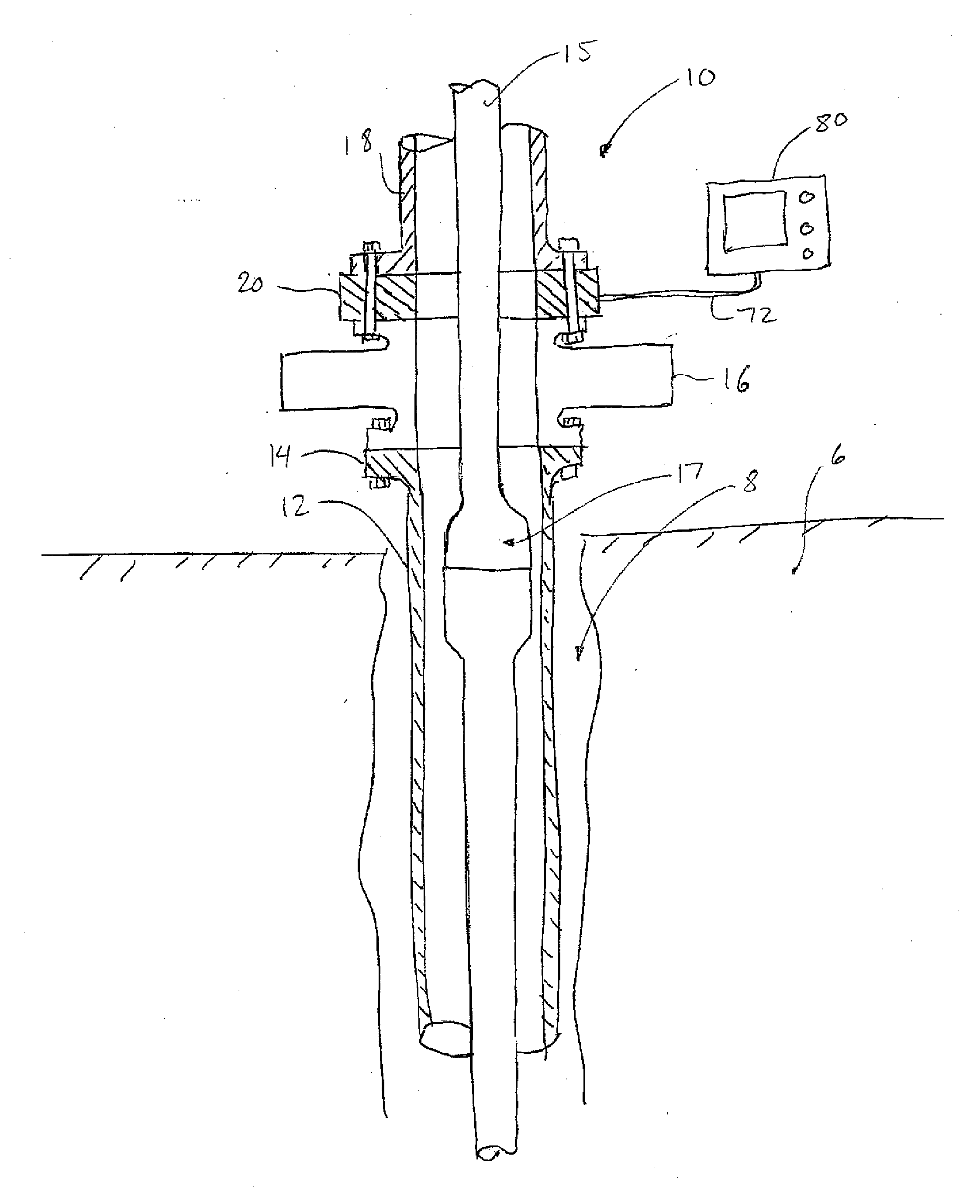
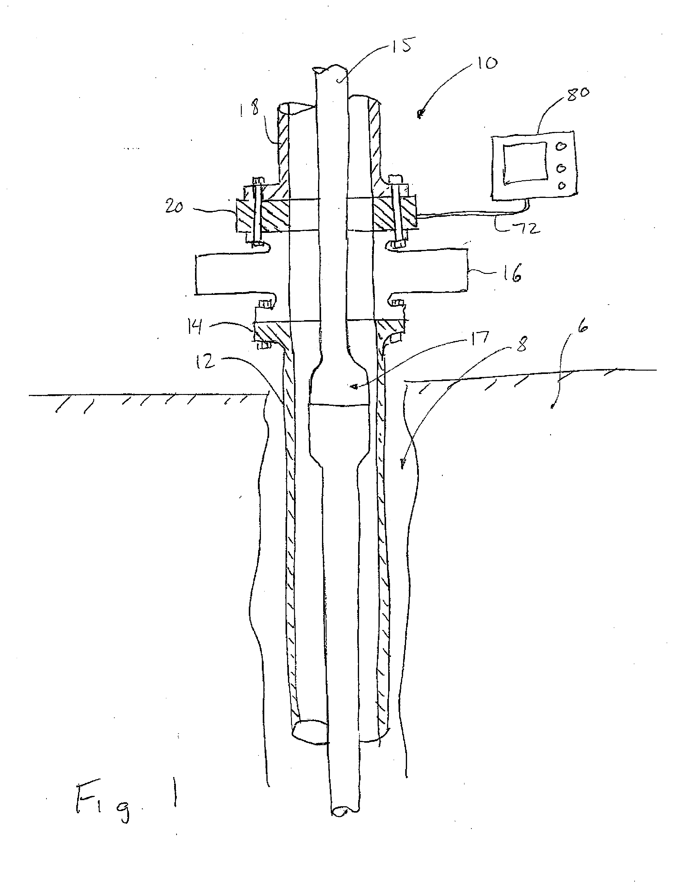
[0019]Referring to FIG. 1, a well assembly located within a well bore 8 of a soil formation 6 is illustrated generally at 10. The well assembly includes a well casing 12 having top flange 14 which is securable to a pipe ram 16 or any other desired well head device. It will be appreciated that the present apparatus may be located at any location within the well, such as, by way of non-limiting example, the casing, snubbing unit, blow out preventer or any other well apparatus. It will also be appreciated that the Although only a single pipe ram is illustrated in FIG. 1 for the sake of clarity, it will be appreciated that many installations will include more than one well head component. As illustrated in FIG. 1, the well assembly includes an apparatus for sensing a pipe joint according to a first embodiment of the invention, shown generally at 20 and one or more top pipe, well component or other equipment 18 located thereabove. A production or tool string 15 is located within the casi...


PUM


Abstract

A system for sensing a pipe joint within a well structure bore comprises a body connectable in line with the well structure. The body has a central bore therethrough and includes a plurality of blind bores extending radially inwards from the outer surface. The system further includes at least one sleeve being locatable within one of the plurality of blind bores wherein each of the sleeves has a magnet located at an end thereof at least one sensor being locatable within one of the at least one sleeves. The at least one sensor is operable to output a signal representing the width of a metallic object located within the central bore. The system may further include a display operable to receive the output signal from the at least one sensor and to display an output to a user indicating the width of the metallic object within the central bore.

Description

BACKGROUND OF THE INVENTION[0001]1. Field of Invention[0002]The present invention relates to well boring in general and in particular to a method and apparatus for sensing a pipe joint within a well structure.[0003]2. Description of Related Art[0004]In hydrocarbon production, a well may be formed by an outer casing located within a wellbore and may optionally be surrounded by cement. The well may then include a tool or production string therein for working or producing from the well. Due to the potentially high pressures within the well from hydrocarbons extracted from the hydrocarbon producing formation, numerous types of shut-off valves, spools and other fittings to isolate and control access to the well, such as, by way of non-limiting example a Christmas tree, as it is commonly known or a snubbing rig.[0005]The well structure may include shut-off valves for closing off or otherwise completely or partially sealing the top of the well as desired by a user. In particular, one commo...

Claims


Application Information

Patent Timeline
IPC IPC(8): G01V3/08
CPCG01V3/08E21B47/092G01B7/12E21B47/085E21B17/04E21B33/061
Inventor CARLSON, AARON MITCHELL
Owner INTELLIGENT WELLHEAD SYST INC
Why Eureka
Try Eureka