

Image forming apparatus
a technology of image forming apparatus and forming apparatus, which is applied in the direction of electrographic process apparatus, instruments, optics, etc., can solve the problems of insufficient amount of air exhausted from within the image forming apparatus, insufficient to deal with “dust” and insufficient to remove all the dust in the apparatus, so as to reduce the effect of as much
- Summary
- Abstract
- Description
- Claims
- Application Information
AI Technical Summary
Benefits of technology
Problems solved by technology
Method used
Image

Examples
embodiment 1
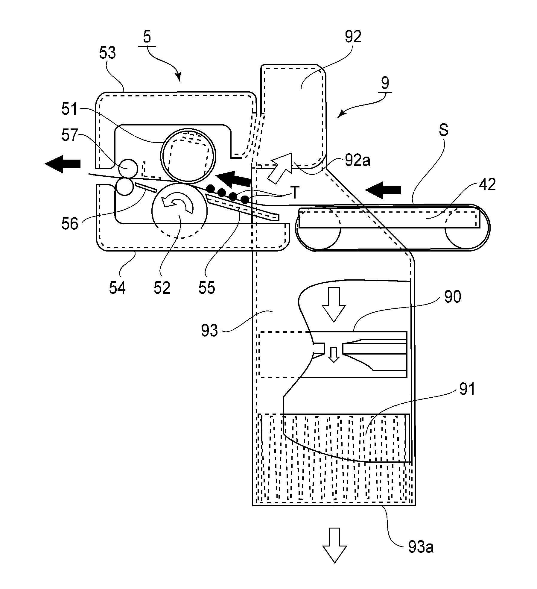
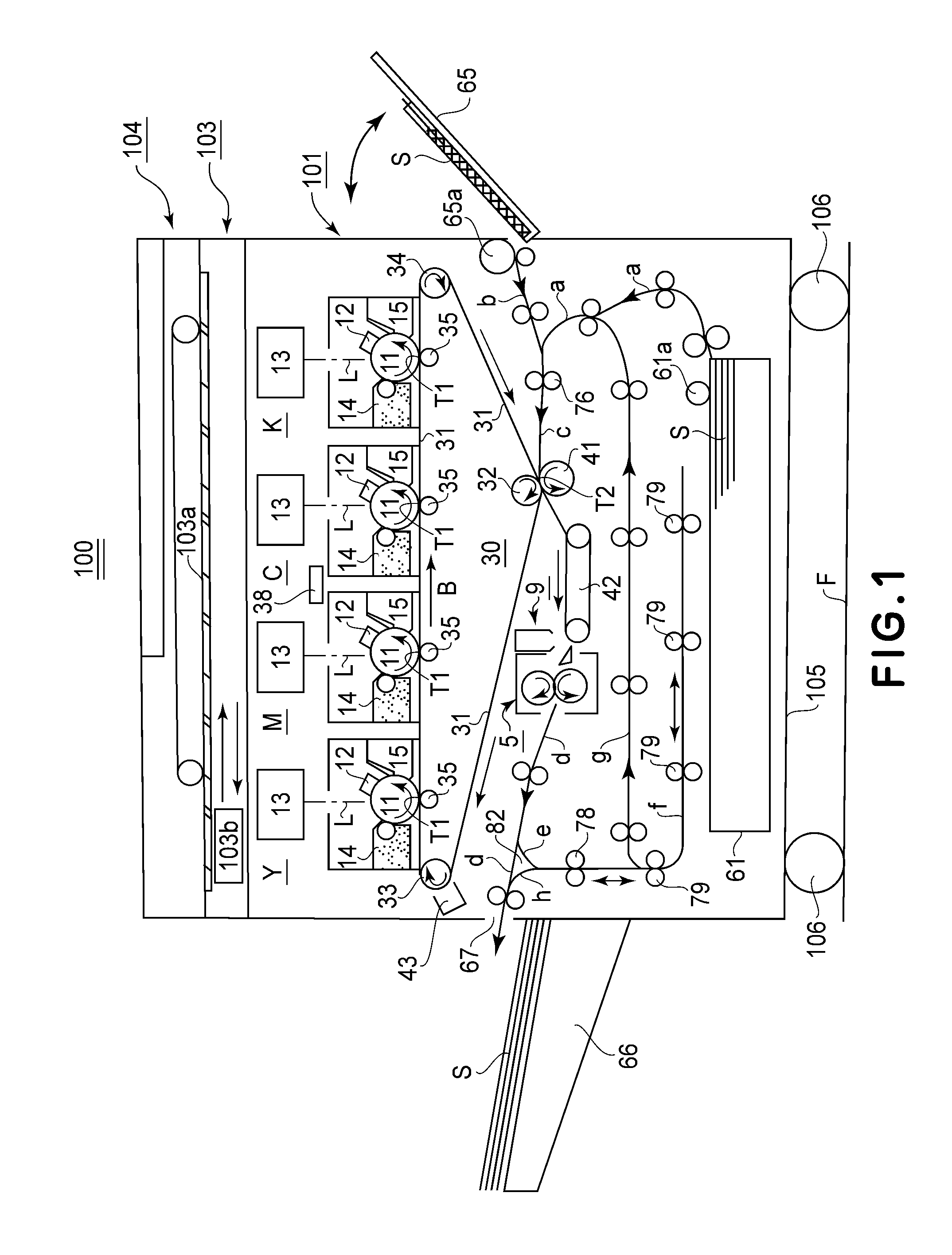
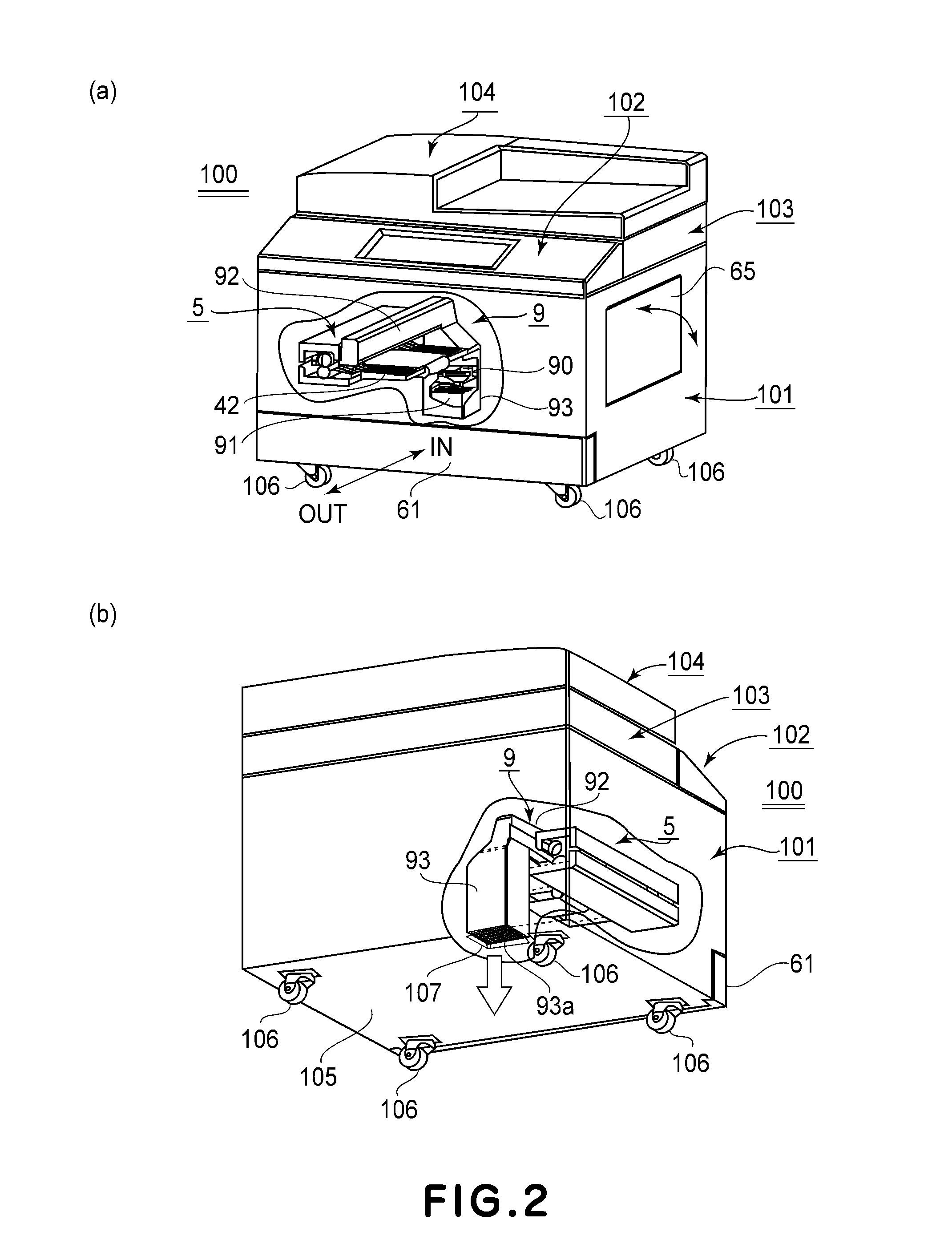
[0029]FIG. 1 is a sectional view of the image forming apparatus 100 in this embodiment, at a vertical plane parallel to the recording medium conveyance direction of the apparatus. FIG. 2(a) is a partially broken external perspective view of the apparatus 100 shown in FIG. 1, as seen from the front side of the apparatus 100. It shows the fixing device (fixing means) 5, air exhausting means 9, and their adjacencies, of the image forming apparatus 100. FIG. 2(b) is an external perspective view of the image forming apparatus 100 in the first embodiment, as seen from the rear side of the apparatus 100, a part of which is intentionally omitted to show the fixing device 5, air exhausting means 9, and their adjacencies, which are in the image forming apparatus 100.
[0030]Regarding the directional references of the image forming apparatus 100 in this embodiment, the front surface side (front side) of the apparatus 100 is the side of the apparatus 100, from which a sheet feeder / storage cassett...
embodiment 2
[0096]In this second embodiment of the present invention, the image forming apparatus is provided with a memory (storage) 202 for storing the date and time when the image forming apparatus was used the last time for image formation, as shown a part of the block diagram for the fan control. FIG. 9 is the flowchart for the fan control in the second embodiment of the present invention.
[0097]Referring to FIG. 9, steps S201 and S202 are the same as steps and S102 of the flowchart in FIG. 8. In the step S203, the control section 200 looks up the date and time when a print was outputted the last time (image forming job was carried out the last time), stored in the memory 202 (FIG. 3). Then, it determines whether or not the current date and time is no less than a preset length of time (long enough for the interior of the image forming apparatus main assembly 101 to sufficiently cool down) past the date and time in the memory (S203).
[0098]If no less than the preset length of time has elapsed...
embodiment 3
[0107]In the third embodiment, the image forming apparatus 100 is provided with a temperature sensor (fixation temperature sensor) STH for detecting the temperature of the adjacencies of the recording medium entrance of the fixing device 5, which is the fixing section, as will be evident from the block diagram of the fan control system (FIG. 3). FIG. 10 is a schematic sectional view of the fixing device 5, exhaust ducts, and their adjacencies, at a plane parallel to the recording medium conveyance direction, as seen from the front side, and FIG. 11 is a flowchart of the control in the third embodiment.
[0108]Referring to FIG. 10, in the third embodiment, the temperature sensor STH which is capable of detecting the ambient temperature of the fixation nip of the fixing device 5 is provided. The control section 200 can directly determine, with the use of this temperature sensor STH, whether or not the fixing device 5 has sufficiently cooled down.
[0109]Referring to FIG. 11, steps S301 an...
PUM
 Abstract
Description
Claims
Application Information