Sealed pipette

a pipette and sealing technology, applied in the field of sealing pipette, can solve the problems of reducing the release force needed, affecting the sealing ring, and often using harmful big forces to attach the tips

Active Publication Date: 2014-02-27
THERMO FISCHER SCI OY
View PDF5 Cites 28 Cited by
  • Summary
  • Abstract
  • Description
  • Claims
  • Application Information

AI Technical Summary

Benefits of technology

[0009]According to another embodiment, and additional attachment mechanism, especially a form closure mechanism, is used. This mechanism may be especially such as comprises attachment claws, e.g. such as described in US 2005/0175511, and EP 2 452 754. The moving sealing ring provides also a special advantage when attaching the pipette t...

Problems solved by technology

In conventional multichannel pipettes dimension differences easily cause leakages in some channels and therefore harmf...

Method used


Image

  • Sealed pipette
  • Sealed pipette
  • Sealed pipette

Examples


Embodiment Construction

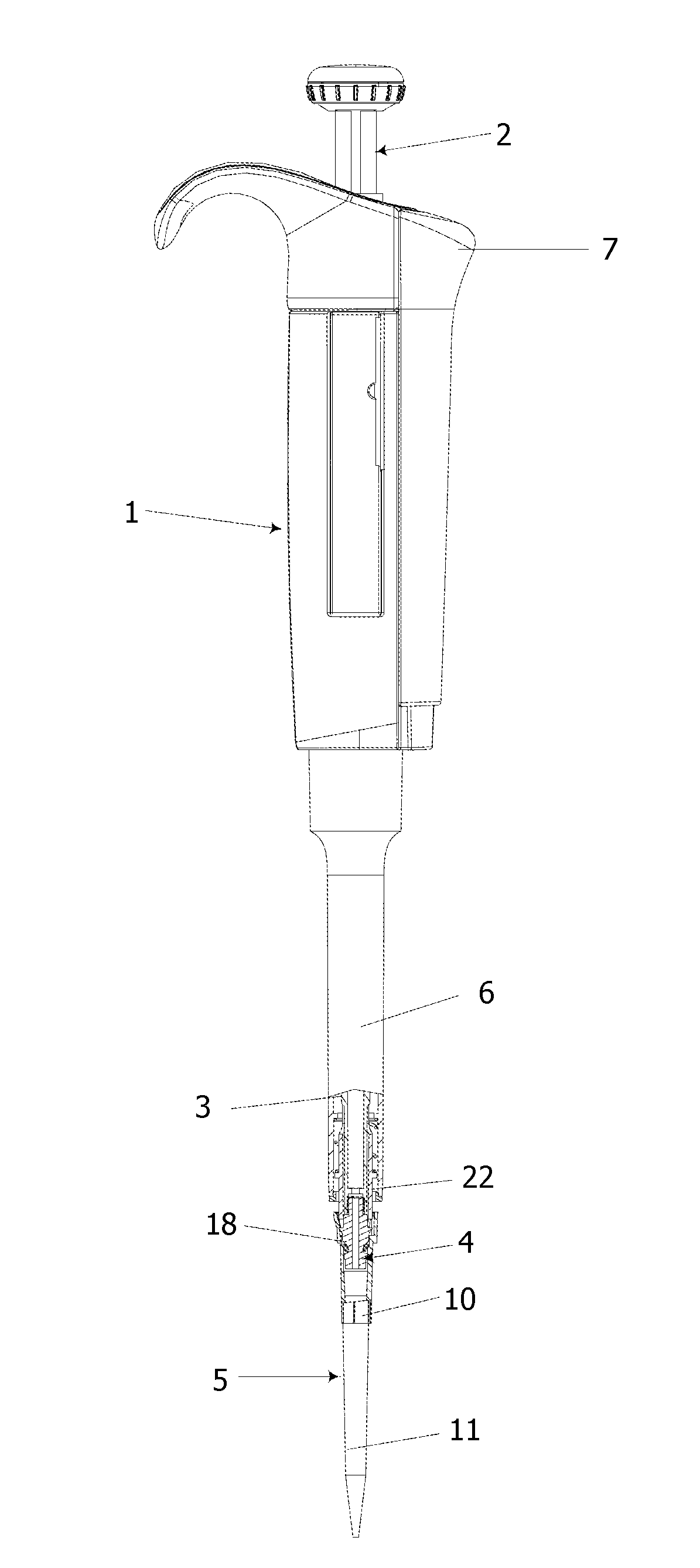
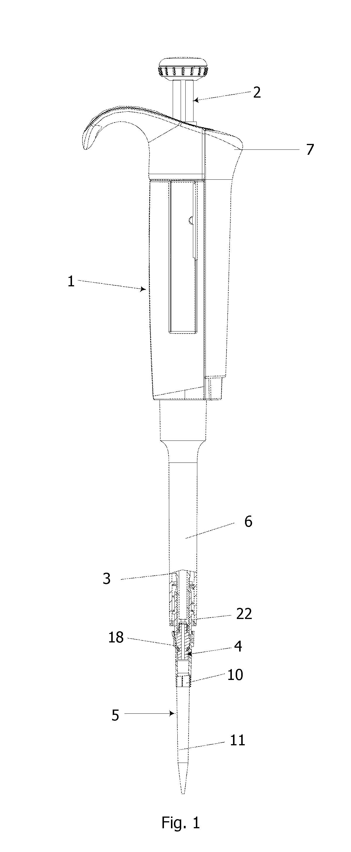
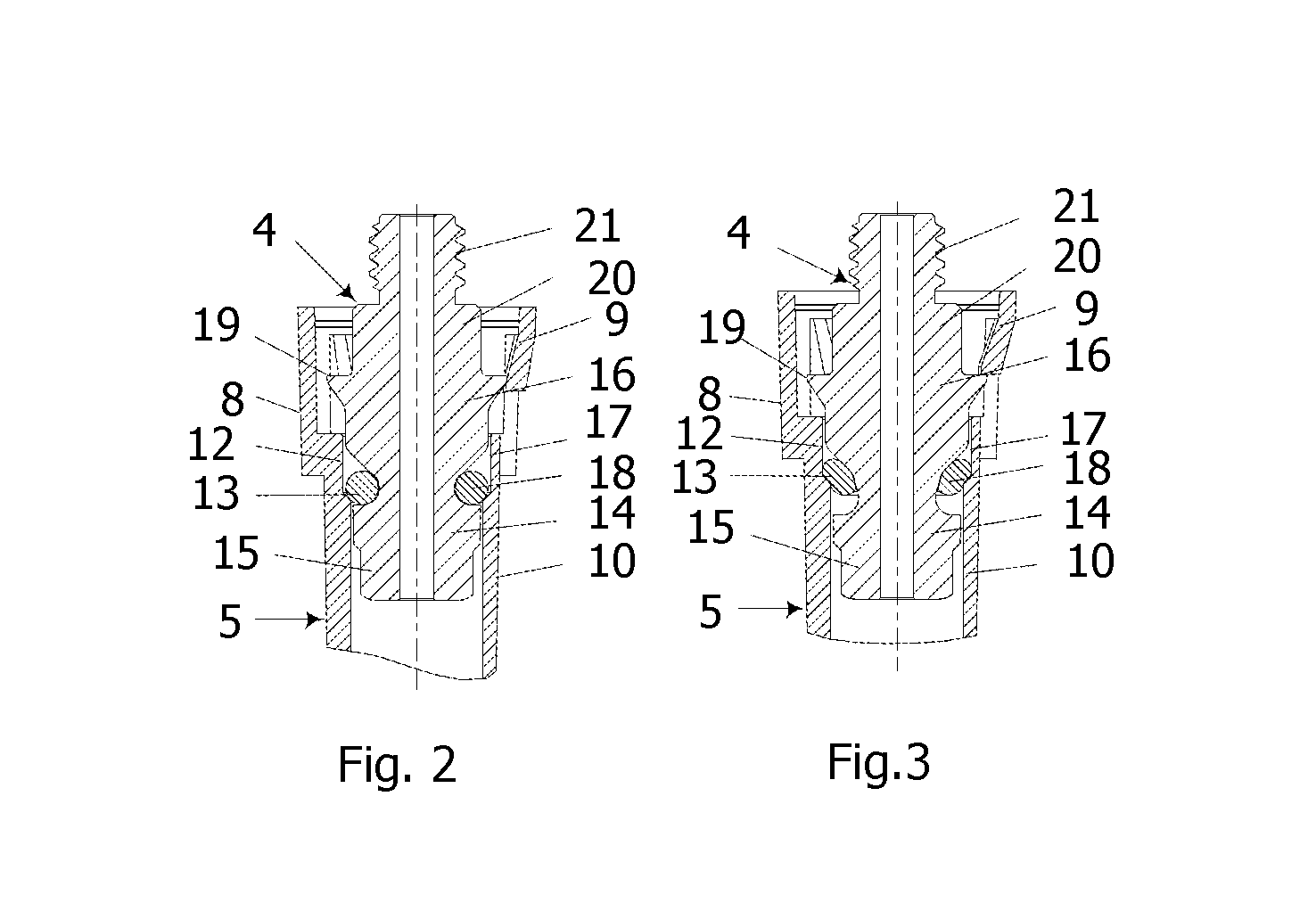
[0017]The pipette in accordance with the figures comprises a handle 1 and inside it a cylinder and a piston movable in it. The piston has an arm 2, the end of which extends out from the upper end of the handle. The arm is connected with a spring, which tends to press the piston to its upper position. The pipette comprises a volume adjustment mechanism, by means of which the stroke length of the piston and thereby the volume of the dispensed liquid can be adjusted by rotating the arm. The set volume is displayed on the side of the handle by digit rings. The cylinder comprises at its lower end an extension channel 3. At the lower end of the extension channel there is a pipette tip mounting piece 4 with an axial channel through it. A pipette tip 5 is attached onto the mounting piece. The mounting piece has been attached to the inside end of the channel by a thread. The pipette comprises also a pipette tip removing mechanism with a tip removal sleeve 6 sliding on the extension channel a...


PUM

PropertyMeasurementUnit
Lengthaaaaaaaaaa
Thicknessaaaaaaaaaa
Widthaaaaaaaaaa

Abstract

The invention relates to liquid dispensing and concerns a pipette comprising at least one aspiration channel with a piston. At the lower end of the aspiration channel there is an extension channel (3) and at its end a pipette tip mounting piece (4) onto which a pipette tip (5) is attached. On the pipette tip mounting piece there is a surrounding groove (17) and in the groove a sealing ring (18). The width of the groove in the axial direction is at least 1.1 times the thickness of the sealing ring in the axial direction. When the mounting piece is pushed into the pipette tip, the inner wall of the tip can move the sealing ring upwards in the groove. The construction can provide a reliable sealing despite of inherent dimension differences between different tips and mounting pieces.

Description

TECHNICAL FIELD[0001]The invention relates to liquid dispensing and concerns a pipette, in which a pipette tip is attached to the lower end of an elongated aspiration channel in which a piston is moved. The lower end of the channel is provided with a surrounding groove and a seal in the groove in order to secure that the tip is tightly attached.TECHNICAL BACKGROUND[0002]For liquid dispensing there are pipettes which comprise a piston by means of which liquid is aspirated into and removed from a pipette tip attached to an aspirating channel. The tip is sealed against the outer surface of the lower tip of the aspiration channel. The sealing is usually carried out so that the material of the tip is softer than that of the lower tip of the aspiration channel, whereby the tip yields and is thus sealed against the surface of the aspiration channel. The sealing may be carried out also, for example, by means of an O-ring in a surrounding groove on the outer surface of the aspiration channel...

Claims


Application Information

Patent Timeline
IPC IPC(8): B01L3/02B01L3/00
CPCB01L3/0275B01L3/021B01L3/0217B01L2200/02B01L2200/025B01L2400/0478G01N35/1074Y10T29/49826
Inventor JAASKELAINEN, ARILIND, MIKAELTELIMAA, JUHATUOMINEN, AARO
Owner THERMO FISCHER SCI OY
Why Eureka
Try Eureka