Can Opener

Active Publication Date: 2014-03-06
LEE HUI LING
View PDF26 Cites 6 Cited by
  • Summary
  • Abstract
  • Description
  • Claims
  • Application Information

AI Technical Summary

Benefits of technology

[0007]According to the primary advantage of the present invention, the can opener separates the lid from the can to open the can automatically so as to save the user's energy so that the user needs not to apply any force to open the can.
[0008]According to another advantage of the present invention, the can opener is revolved along the rim of the lid to separate the lid from the can and stops operating when the lid is separated from the can so that the user needs not to hold the can and the can opener during the opening process, thereby facilitating the user operating the can opener to open the can.
[0009]According to a further advantage of the present invention, the lid is directly separate

Problems solved by technology

However, the user has to apply a larger force on the handle of the can opener so as to rotate the handle of the can opener relative to the can, thereby wasting the user's

Method used


Image

  • Can Opener
  • Can Opener
  • Can Opener

Examples


Embodiment Construction

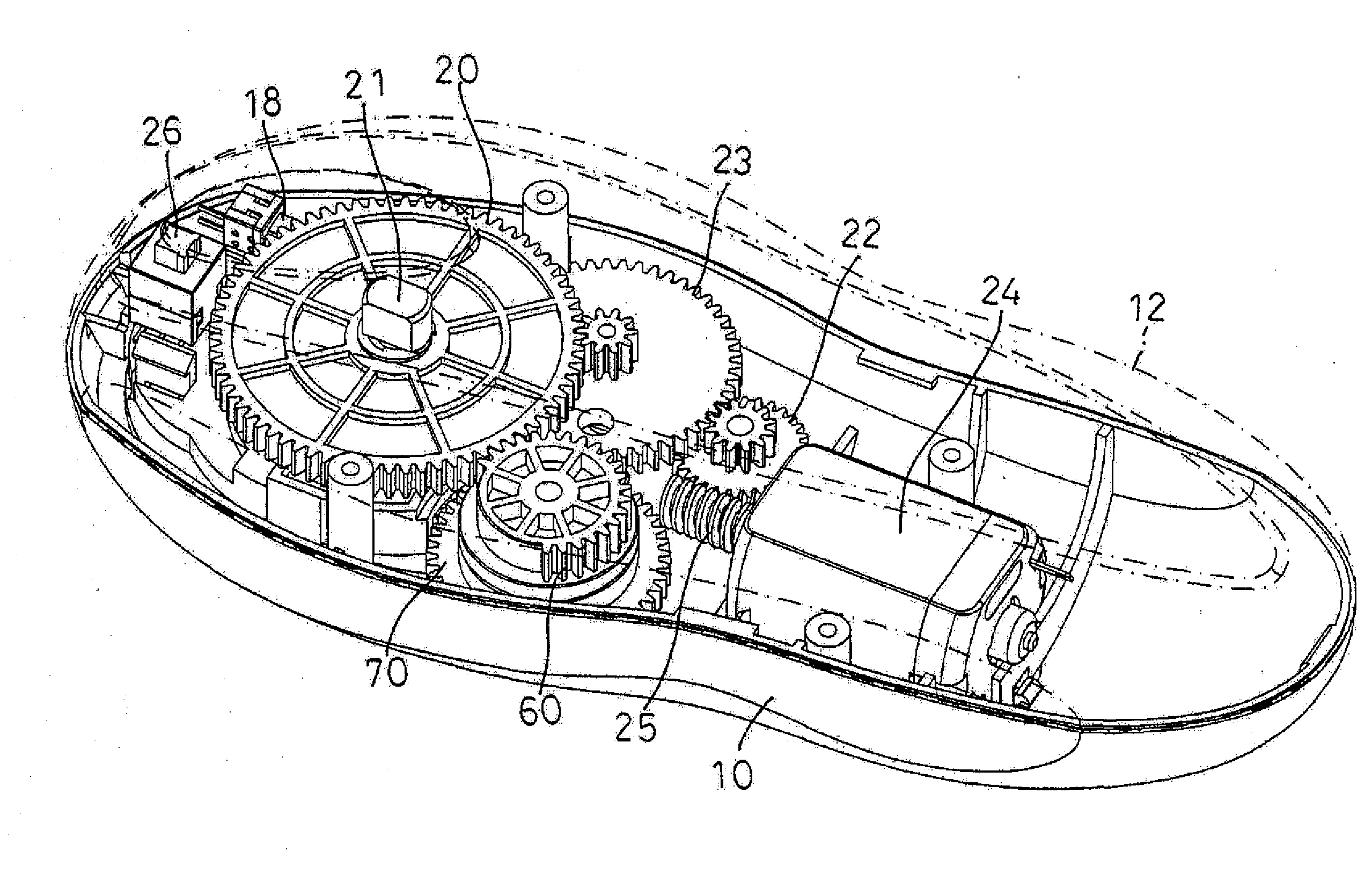
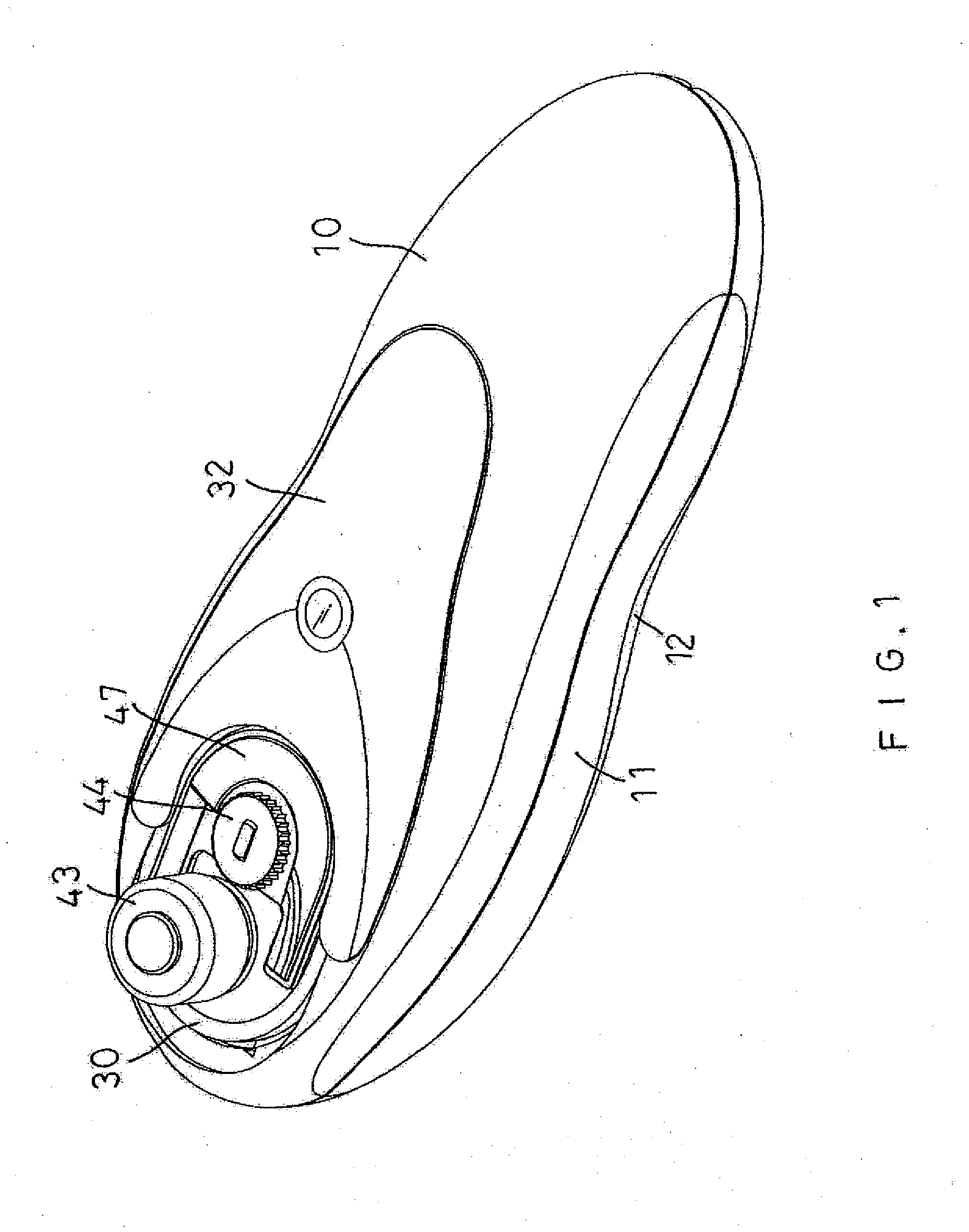
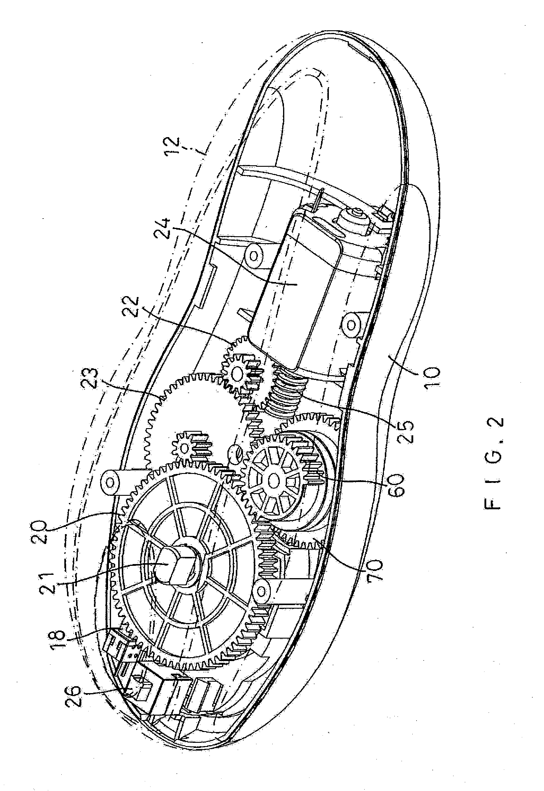
[0017]Referring to FIGS. 1-5, a can opener in accordance with the preferred embodiment of the present invention comprises a housing 10 having an interior provided with a mounting seat 14, a driving gear 20 rotatably mounted on the mounting seat 14 of the housing 10, a reduction transmission device 2 mounted in the housing 10 and connected with the driving gear 20 to drive the driving gear 20, a cutting wheel 44 rotatably mounted on the housing 10 and rotated in concert with the driving gear 20, a driving shaft 21 rotatably mounted in the housing 10 and having a first end connected with the driving gear 20 and a second end connected with the cutting wheel 44, a microswitch 18 mounted on the mounting seat 14 of the housing 10, a slide 30 movably mounted on the mounting seat 14 of the housing 10 and having a surface provided with an aperture 36, a washer 46 secured on a bottom of the slide 30 to move in concert with the slide 30, a metallic plate 47 mounted on the driving shaft 21 and ...


PUM


Abstract

A can opener includes a housing, a driving gear, a reduction transmission device, a cutting wheel, a slide, an idling wheel, a first driven gear, a second driven gear, a torsion spring, a third driven gear, and a cam. The driving gear rotates the cutting wheel and the first driven gear. The first driven gear drives the second driven gear which rotates the third driven gear which rotates the cam which moves the slide which moves the idling wheel so that the idling wheel is moved toward the cutting wheel to clamp the rim of the lid between the idling wheel and the cutting wheel. The idling wheel and the cutting wheel are moved along the rim of the lid to cut the rim of the lid and to separate the lid from the can so as to open the can automatically.

Description

BACKGROUND OF THE INVENTION[0001]1. Field of the Invention[0002]The present invention relates to an opening tool and, more particularly, to an opener for opening the lid of a container, such as a can and the like.[0003]2. Description of the Related Art[0004]A conventional can opener comprises a handle, and a cutter mounted on the handle. The cutter has a side provided with a resting portion and a blade. When in use, the cutter of the can opener is placed on the lid of a can, with the resting portion of the cutter abutting the outer rim of the lid, and with the blade of the cutter abutting the inner rim of the lid. When the handle of the can opener is rotated by the user, the blade of the cutter penetrates the lid of the can to form a hole in the surface of the lid. Then, the handle of the can opener is rotated successively, and the blade of the cutter is moved along the inner rim of the lid to perform a circular motion so as to form an elongate groove in the surface of the lid. Afte...

Claims


Application Information

Patent Timeline
IPC IPC(8): B67B7/72
CPCB67B7/385
Inventor LEE, HUI-LING
Owner LEE HUI LING
Why Eureka
Try Eureka