
Pressure sensor and pressure sensing method

a pressure sensor and pressure sensing technology, applied in the direction of force measurement, instruments, force measurement, etc., can solve the problems of difficult to apply such materials to pressure sensors for electronic skins, applied to flexible substrates, and not having excellent piezoelectric characteristics

Active Publication Date: 2014-03-06
SAMSUNG ELECTRONICS CO LTD +1
View PDF6 Cites 57 Cited by
  • Summary
  • Abstract
  • Description
  • Claims
  • Application Information

AI Technical Summary

Benefits of technology

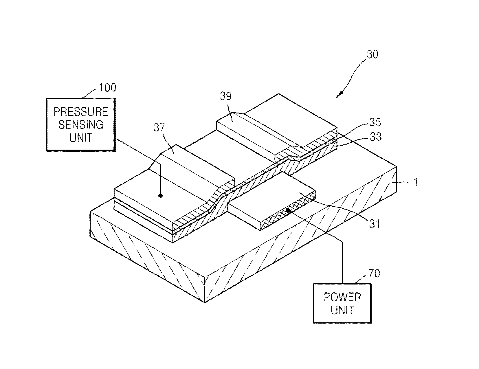
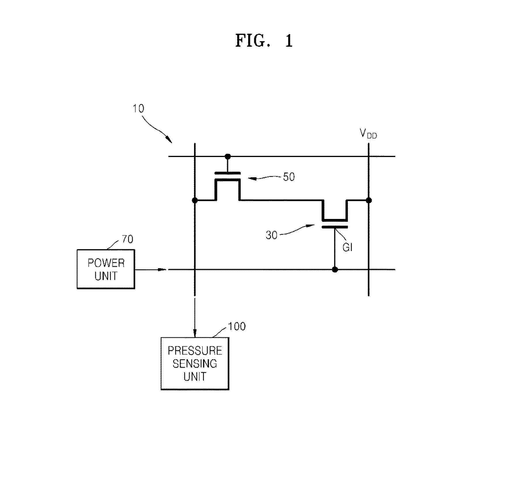
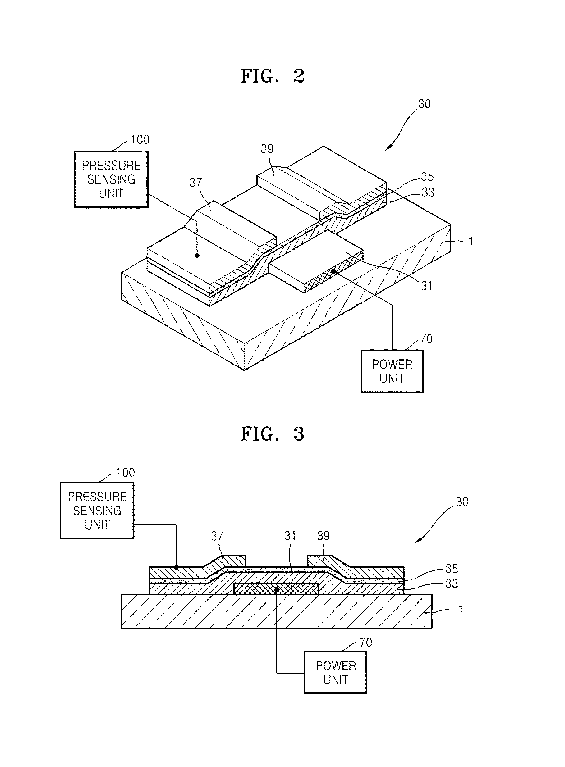
This patent describes a pressure sensor that uses a flexible substrate and thin film transistors (TFTs) to detect pressure. The sensor includes a sensor TFT with a piezoelectric gate insulating layer made of an organic matrix with piezoelectric inorganic nano-particles dispersed throughout. The organic matrix is made of a piezoelectric organic material such as P(VDF-TrFE) or P(VDF-TrFE-CFE). The sensor applies an alternating current (AC) signal to the gate of the sensor TFT and detects a drain current generated in response to the AC signal. The drain current is proportional to the AC signal amplitude and is used to sense pressure based on the remnant polarization value. The pressure sensor can be used in various applications such as medical diagnosis or sports equipment.

Problems solved by technology

Related art organic materials may be manufactured on a flexible substrate through a low temperature process; however, they do not have excellent piezoelectric characteristics.
On the other hand, related art inorganic materials may have excellent piezoelectric characteristics; however, they may be applied to a hard substrate but may not be applied to a flexible substrate because a high temperature process is necessary.
That is, the organic and inorganic materials both have technical issues making it difficult for such materials to be applied to pressure sensors for an electronic skin.

Method used


Image

  • Pressure sensor and pressure sensing method
  • Pressure sensor and pressure sensing method
  • Pressure sensor and pressure sensing method

Examples


Embodiment Construction

[0041]Reference will now be made in detail to exemplary embodiments, examples of which are illustrated in the accompanying drawings, wherein like reference numerals refer to like elements throughout. In this regard, the present exemplary embodiments may have different forms and should not be construed as being limited to the descriptions set forth herein. Accordingly, the exemplary embodiments are merely described below, by referring to the figures, to explain aspects of the present description. It will be understood that when an element or layer is referred to as being “on” another element or layer, the element or layer can be directly on another element or layer or intervening elements or layers. Expressions such as “at least one of,” when preceding a list of elements, modify the entire list of elements and do not modify the individual elements of the list.

[0042]FIG. 1 is an equivalent circuit diagram schematically showing a pressure sensor 10 according to an exemplary embodiment,...


PUM

PropertyMeasurementUnit
frequencyaaaaaaaaaa
voltage amplitudeaaaaaaaaaa
temperatureaaaaaaaaaa

Abstract

A pressure sensor and a pressure sensing method are provided. The pressure sensor includes a substrate; a sensor thin film transistor (TFT) disposed on the substrate and including a gate insulating layer, wherein the gate insulating layer includes an organic matrix in which piezoelectric inorganic nano-particles are dispersed; a power unit configured to apply an alternating current (AC) signal to a gate of the sensor TFT; and a pressure sensing unit configured to obtain a remnant polarization value based on a drain current which is generated in response to the AC signal and detected by the sensor TFT, and to sense a pressure based on the remnant polarization value.

Description

CROSS-REFERENCE TO RELATED APPLICATION[0001]This application claims the priority of Korean Patent Application No. 10-2012-0098486, filed on Sep. 5, 2012, in the Korean Intellectual Property Office, the disclosure of which is incorporated herein in its entirety by reference.BACKGROUND[0002]1. Field[0003]The present disclosure relates to pressure sensors and pressure sensing methods thereof, and more particularly, to pressure sensors integrated as thin film transistors (TFTs) and pressure sensing methods thereof.[0004]2. Description of the Related Art[0005]In order to realize flexible electronic components, components and materials for forming the components have to be mechanically reliable, as well as have excellent electric characteristics. To achieve these flexible electronic components, much research into material science / engineering has been conducted. Such technology may be applied to stretchable electronic components, as well as flexible electronic components.[0006]Related art ...

Claims


Application Information

Patent Timeline
Patent Type & Authority Applications(United States)
IPC IPC(8): G01L1/16H01L29/84
CPCH01L29/84G01L1/16G01L9/06
Inventor JEON, SANG-HUNPARK, JONG-JINNGUYEN, THANH TIENBAE, JI-HYUNBYUN, KYUNG-EUNLEE, NAE-EUNGKIM, DO-ILTRAN, QUANG TRUNG
Owner SAMSUNG ELECTRONICS CO LTD
Learn More