Water cooled internal combustion engine for vehicle

a technology of internal combustion engine and water cooling, which is applied in the direction of machines/engines, mechanical equipment, automatic control, etc., can solve the problems of internal combustion engine size increase in the direction of the crankshaft, internal combustion engine injury, etc., and achieve the effect of compact size and improved external appearan

Active Publication Date: 2014-03-06
HONDA MOTOR CO LTD
View PDF6 Cites 10 Cited by
  • Summary
  • Abstract
  • Description
  • Claims
  • Application Information

AI Technical Summary

Benefits of technology

[0007]The present invention has been made in view of the above described circumstances, and has an objective according to an embodiment of providing a water cooled internal combustio

Problems solved by technology

Accordingly, tightening members arranged on an outer periphery of the pump cover remain exposed outside whereby there is a possibility of injuring an

Method used


Image

  • Water cooled internal combustion engine for vehicle
  • Water cooled internal combustion engine for vehicle
  • Water cooled internal combustion engine for vehicle

Examples


Embodiment Construction

[0035]The embodiment of the present invention will be described hereunder with reference to accompanying drawings of FIG. 1 to FIG. 9. In the following description, the orientation such as front, rear, upper, lower, left and right is set on the basis of a rider riding on a motorcycle.

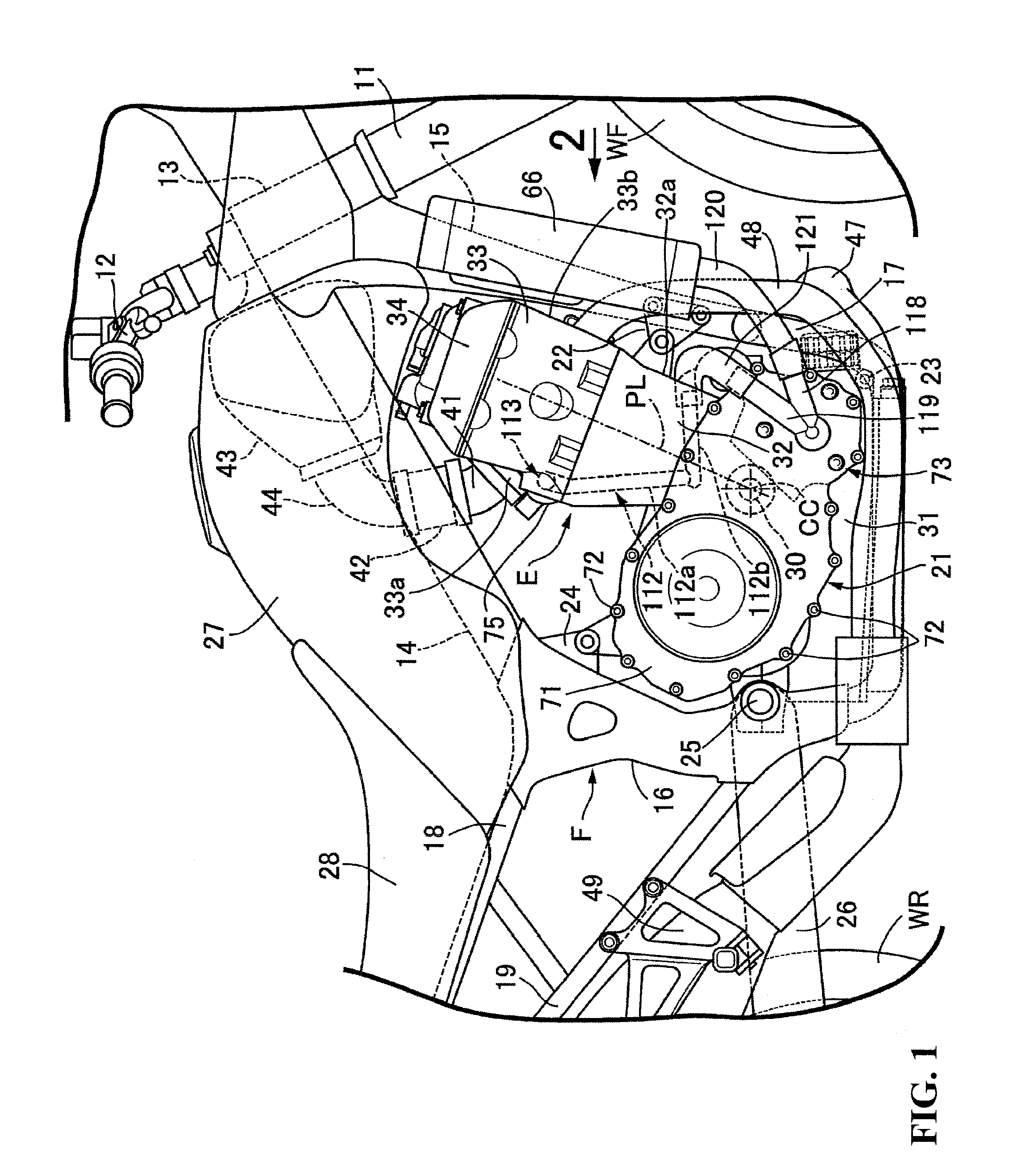
[0036]Referring first to FIGS. 1 and 2, a vehicle body frame F of the motorcycle includes a head pipe 13 that steerably supports a front fork 11 for pivotally carrying a front wheel WF and a bar-shaped steering handle 12 with a pair of left and right main frames 14 extending rearwardly and downwardly from the head pipe 13. A single down tube 15 extends rearwardly and downwardly from the head pipe 13 at a steeper angle than the main frames 14. A pair of left and right pivot frames 16 extend downwardly from rear end portions of the main frames 14 with a pair of left and right lower frames 17 connecting a lower end portion of the down tube 15 and lower end portions of the pivot frames 16. A pair of left an...


PUM


Abstract

A compact water cooled internal combustion engine for a vehicle wherein a water pump operated by a pump driving shaft is arranged on a crankcase cover for covering a lateral side of a crankcase, such that an axis of rotation of the water pump is coaxial with the pump driving shaft. A case member that forms a pump case of a water pump, together with a crankcase cover, and that rotatably supports a pump shaft of the water pump, is attached on an inner surface side of the crankcase cover.

Description

CROSS-REFERENCE TO RELATED APPLICATIONS[0001]The present application claims priority under 35 USC 119 to Japanese Patent Application No. 2012-191525 filed Aug. 31, 2012 the entire contents of which are hereby incorporated by reference.BACKGROUND OF THE INVENTION[0002]1. Field of the Invention[0003]The present invention relates to a water cooled internal combustion engine for a vehicle, wherein a crankcase cover for covering a lateral side of a crankcase is attached to the crankcase that forms a portion of an engine main body mounted on a vehicle body frame and that rotatably supports a crankshaft. A pump driving shaft, operated by power transmitted from the crankshaft, is rotatably supported on an axis parallel to the crankshaft by the crankcase. A water pump to be driven through the pump driving shaft has an axis of rotation that is coaxial with the pump driving shaft and is arranged on the crankcase cover.[0004]2. Description of Background Art[0005]A water cooled internal combusti...

Claims


Application Information

Patent Timeline
IPC IPC(8): F01P5/10
CPCF01P5/10F02F7/007F02B61/02F02P5/12
Inventor IIDA, AKIHIROMORI, YUICHI
Owner HONDA MOTOR CO LTD
Why Eureka
Try Eureka