In situ combustion for steam recovery infill

Active Publication Date: 2014-03-06
CONOCOPHILLIPS CO
View PDF6 Cites 2 Cited by
  • Summary
  • Abstract
  • Description
  • Claims
  • Application Information

AI Technical Summary

Problems solved by technology

Bitumen recovery from oil sands presents technical and economic challenges due to high viscosity of the bitumen at reservoir conditions.
Re

Method used


Image

  • In situ combustion for steam recovery infill
  • In situ combustion for steam recovery infill
  • In situ combustion for steam recovery infill

Examples


Embodiment Construction

[0015]Turning now to the detailed description of the preferred arrangement or arrangements of the present invention, it should be understood that the inventive features and concepts may be manifested in other arrangements and that the scope of the invention is not limited to the embodiments described or illustrated. The scope of the invention is intended only to be limited by the scope of the claims that follow.

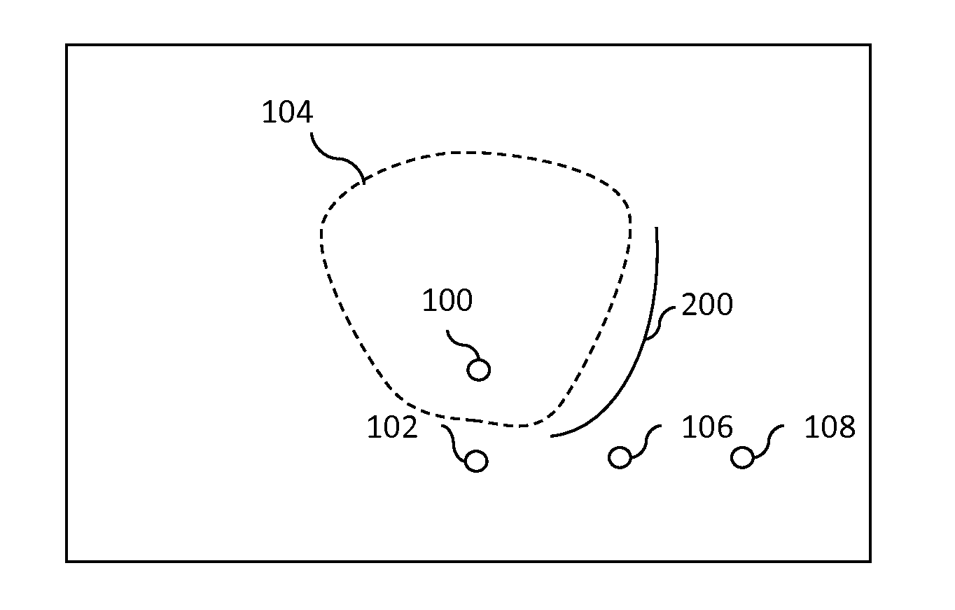
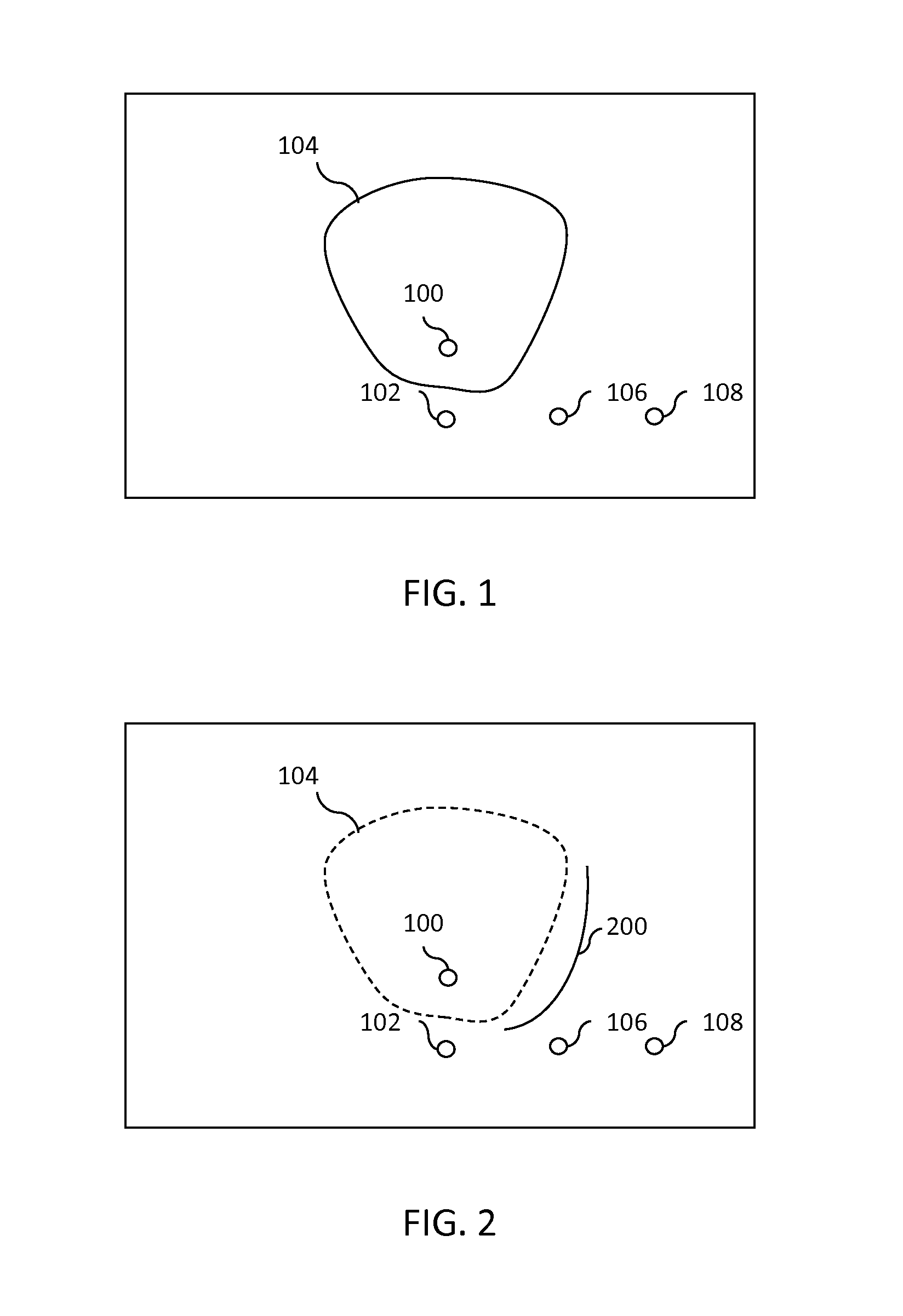
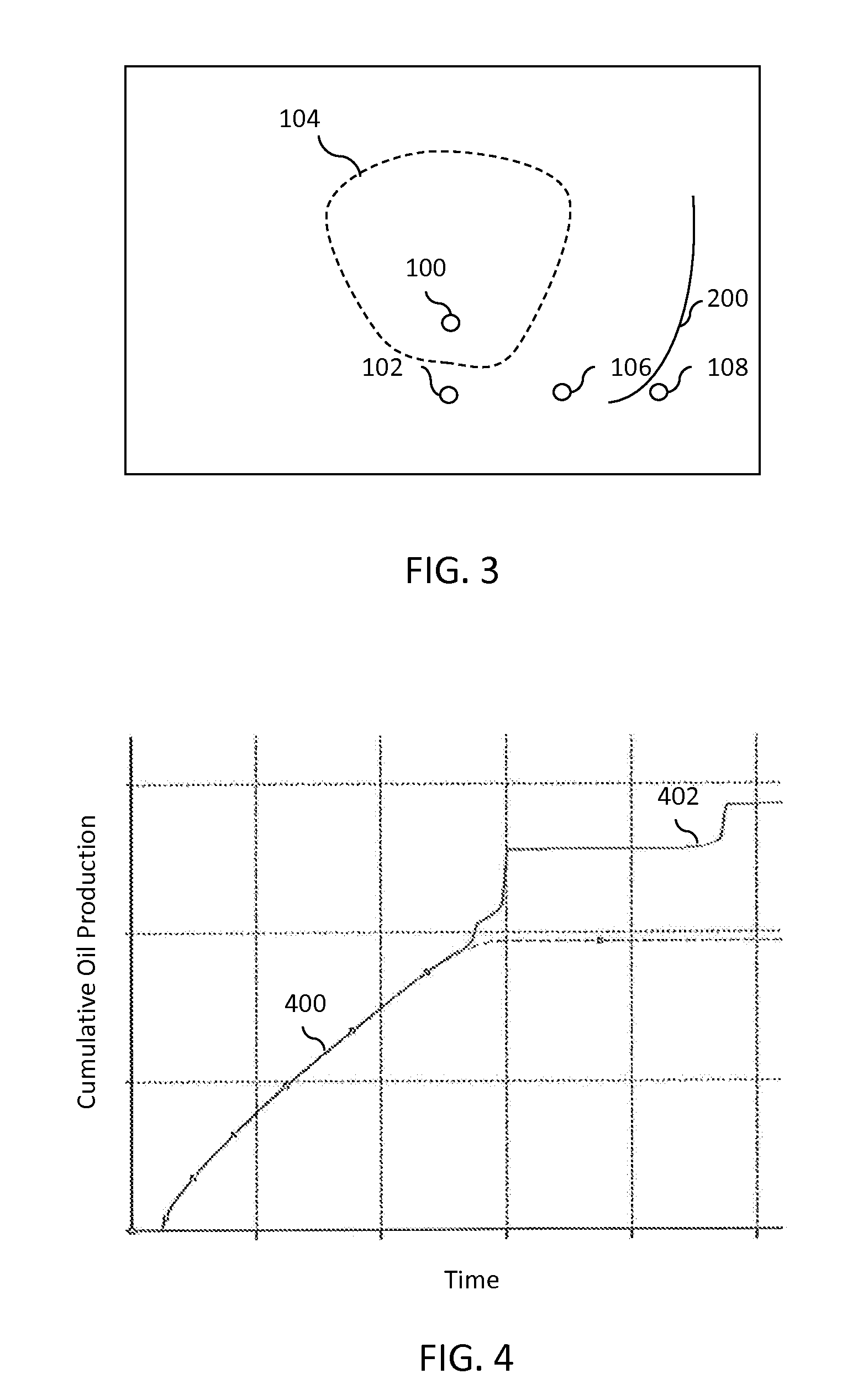
[0016]For some embodiments, methods and systems produce petroleum products from a formation by a steam assisted process followed by an in situ combustion process. The steam assisted process utilizes an injector and first producer to form a steam chamber within the formation as the products are recovered. The in situ combustion then starts by injecting an oxidant into the formation and ignition of residual products. A combustion front advances toward a second producer that may be offset in a lateral direction from the first producer. Heat and pressure from the in situ combusti...


PUM


Abstract

Methods and systems produce petroleum products from a formation by a steam assisted process followed by an in situ combustion process. The steam assisted process utilizes an injector and first producer to form a steam chamber within the formation as the products are recovered. The in situ combustion then starts by injecting an oxidant into the formation and ignition of residual products. A combustion front advances toward a second producer that may be offset in a lateral direction from the first producer. Heat and pressure from the in situ combustion sweeps the products ahead of the combustion front to the second producer for recovery.

Description

CROSS-REFERENCE TO RELATED APPLICATIONS[0001]This application is a non-provisional application which claims benefit under 35 USC §119(e) to U.S. Provisional Application Ser. No. 61 / 693,923 filed Aug. 28, 2012, entitled “IN SITU COMBUSTION FOR STEAM RECOVERY INFILL,” which is incorporated herein in its entirety.STATEMENT REGARDING FEDERALLY SPONSORED RESEARCH OR DEVELOPMENT[0002]None.FIELD OF THE INVENTION[0003]Embodiments of the invention relate to producing hydrocarbons by steam assisted processes and in situ combustion.BACKGROUND OF THE INVENTION[0004]Bitumen recovery from oil sands presents technical and economic challenges due to high viscosity of the bitumen at reservoir conditions. The viscosity of the bitumen prevents the bitumen from flowing in a reservoir. Various stimulation approaches exist to make the bitumen mobile enough for production from a wellbore.[0005]Steam assisted gravity drainage (SAGD) provides one process for producing the bitumen. During SAGD operations, st...

Claims


Application Information

Patent Timeline
IPC IPC(8): E21B43/243
CPCE21B43/243E21B43/2408
Inventor SULTENFUSS, DANIEL RAYDREHER, JR., WAYNE REID
Owner CONOCOPHILLIPS CO
Why Eureka
Try Eureka