Direct steam generation co2 output control

Inactive Publication Date: 2014-03-06
CONOCOPHILLIPS CO
View PDF2 Cites 10 Cited by
  • Summary
  • Abstract
  • Description
  • Claims
  • Application Information

AI Technical Summary

Problems solved by technology

However, desired concentrations of the carbon dioxide within the steam to achieve such benefits for any particular SAGD application may not coincide with output fr

Method used


Image

  • Direct steam generation co2 output control
  • Direct steam generation co2 output control

Examples


Embodiment Construction

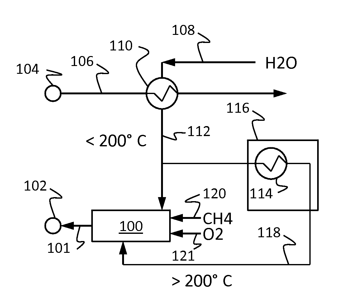
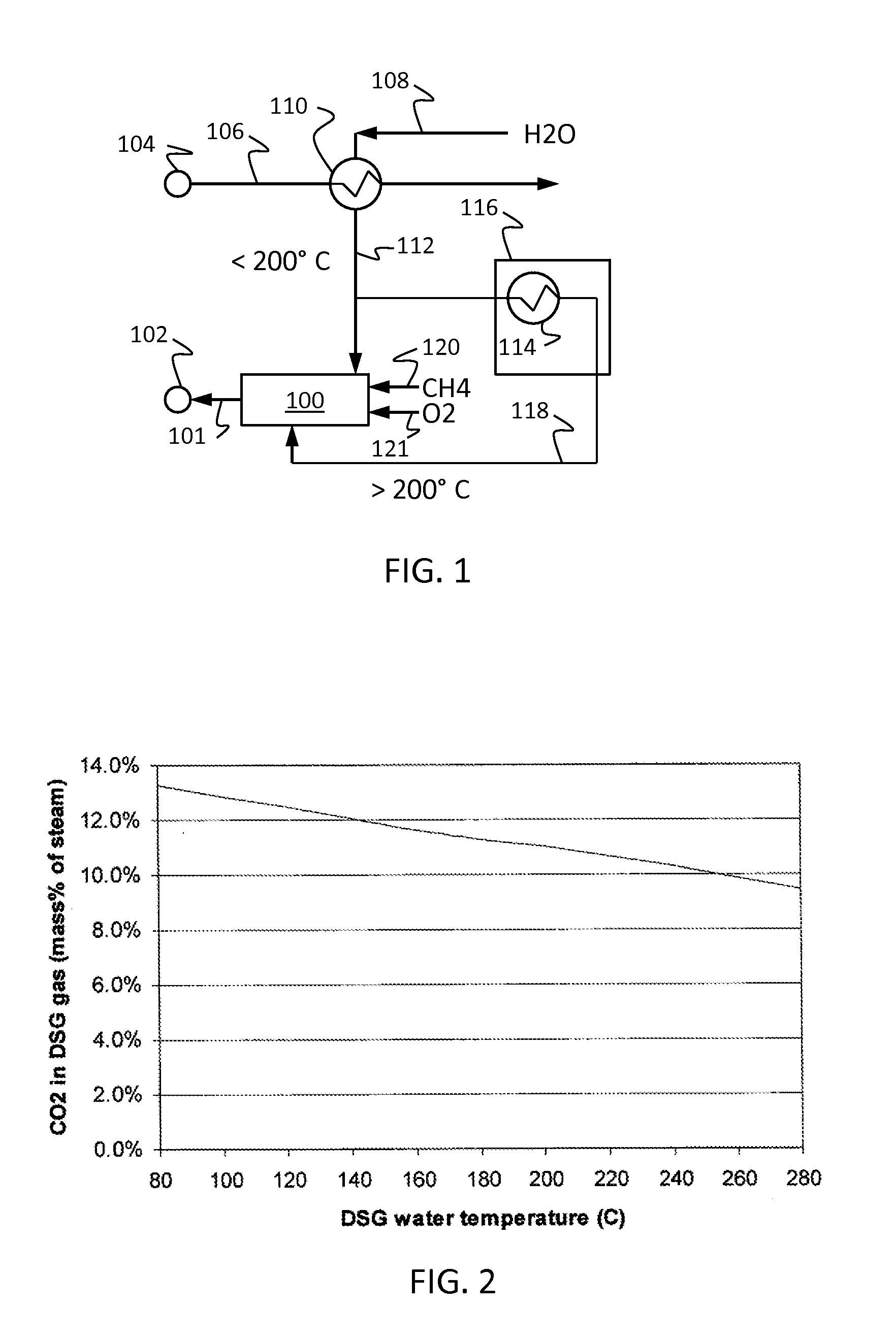
[0014]Turning now to the detailed description of the preferred arrangement or arrangements of the present invention, it should be understood that the inventive features and concepts may be manifested in other arrangements and that the scope of the invention is not limited to the embodiments described or illustrated. The scope of the invention is intended only to be limited by the scope of the claims that follow.

[0015]For some embodiments, methods and systems generate steam and carbon dioxide mixtures suitable for injection to assist in recovering hydrocarbons from oil sands based on concentration of the carbon dioxide in the mixtures as influenced by temperature of water introduced into a direct steam generator. Increasing temperature of the water to above 200° C. before introduction into the direct steam generator may utilize heat from an electrical power generation unit. Enthalpy of this preheated water impacts amount of fuel needed to burn in the direct steam generator and hence ...


PUM


Abstract

Methods and systems generate steam and carbon dioxide mixtures suitable for injection to assist in recovering hydrocarbons from oil sands based on concentration of the carbon dioxide in the mixtures as influenced by temperature of water introduced into a direct steam generator. Increasing temperature of the water to above 200° C. before introduction into the direct steam generator may utilize heat from an electrical power generation unit. Enthalpy of this preheated water impacts amount of fuel needed to burn in the direct steam generator and hence the concentration of the carbon dioxide, which may be below 11% by mass percent of the steam.

Description

CROSS-REFERENCE TO RELATED APPLICATIONS[0001]This application is a non-provisional application which claims benefit under 35 USC §119(e) to U.S. Provisional Application Ser. No. 61 / 697,026 filed Sep. 5, 2012, entitled “DIRECT STEAM GENERATION CO2 OUTPUT CONTROL,” which is incorporated herein in its entirety.STATEMENT REGARDING FEDERALLY SPONSORED RESEARCH OR DEVELOPMENT[0002]None.FIELD OF THE INVENTION[0003]Embodiments of the invention relate to generating a stream containing steam and carbon dioxide for injection during steam assisted hydrocarbon recovery processes.BACKGROUND OF THE INVENTION[0004]Steam assisted gravity drainage (SAGD) provides an exemplary steam assisted recovery process for producing bitumen within oil sands. During SAGD operations, steam introduced into a reservoir through a horizontal injector well transfers heat to the bitumen upon condensation. The bitumen with reduced viscosity due to this heating drains together with steam condensate and is recovered via a ...

Claims


Application Information

Patent Timeline
IPC IPC(8): F22D1/40E21B43/24E21B43/16F22D1/16
CPCF22D1/40E21B43/164E21B43/2406F22D1/16F01K21/04F22B1/26Y02E20/34
Inventor MACADAM, SCOTTSEABA, JAMES
Owner CONOCOPHILLIPS CO
Why Eureka
Try Eureka