
Panel member locking device

a technology of locking device and panel member, which is applied in the direction of fastening means, sheet joining, couplings, etc., can solve the problems of affecting further re-installation operation, affecting the installation of the panel member, and the tiny tie screw may be easily missed, so as to facilitate installation and lock and unlock operations, ensure a high level of locking stability and tightness, and avoid missing component parts during installation or locking/unlocking operations

Inactive Publication Date: 2014-03-06
HANWIT PRECISION IND LTD
View PDF10 Cites 12 Cited by
  • Summary
  • Abstract
  • Description
  • Claims
  • Application Information

AI Technical Summary

Benefits of technology

The present invention is a panel member locking device that is easy to install, secure, and avoids missing parts during locking or unlocking. The main goal is to provide a high level of stability and tightness for the panel member.

Problems solved by technology

The screw nails of the fastening devices may fall from the panel members and missed easily due to user's negligence during a panel member dismounting procedure, affecting further re-installation operation.
Further, these tiny tie screws may be missed easily during the mounting or dismounting operation.

Method used


Image

  • Panel member locking device
  • Panel member locking device
  • Panel member locking device

Examples


Embodiment Construction

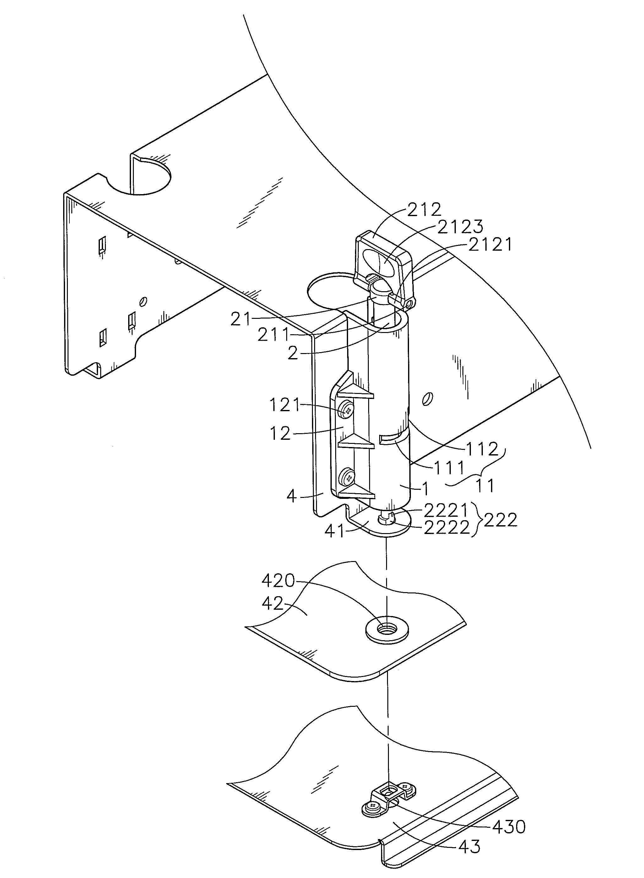
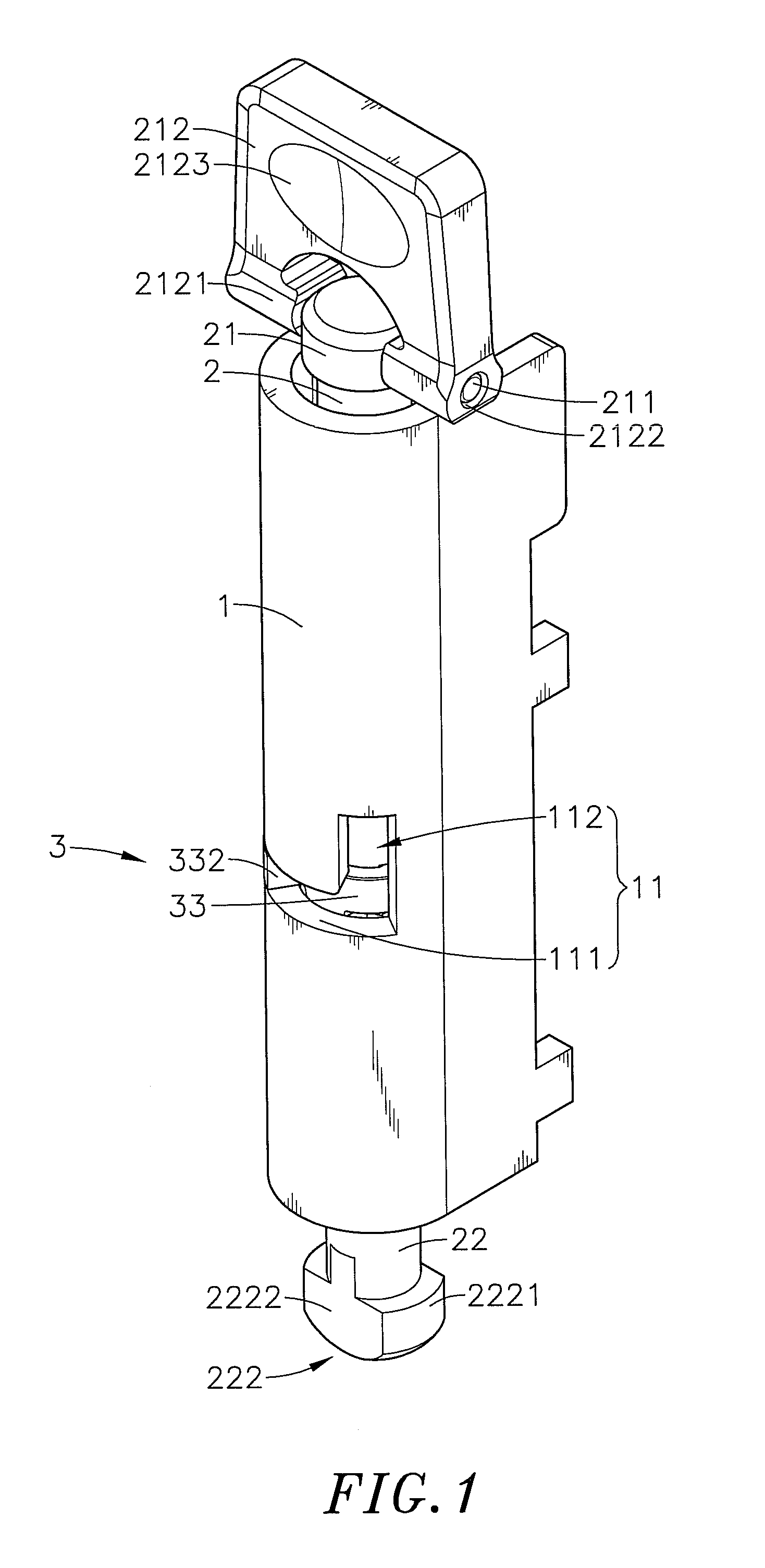
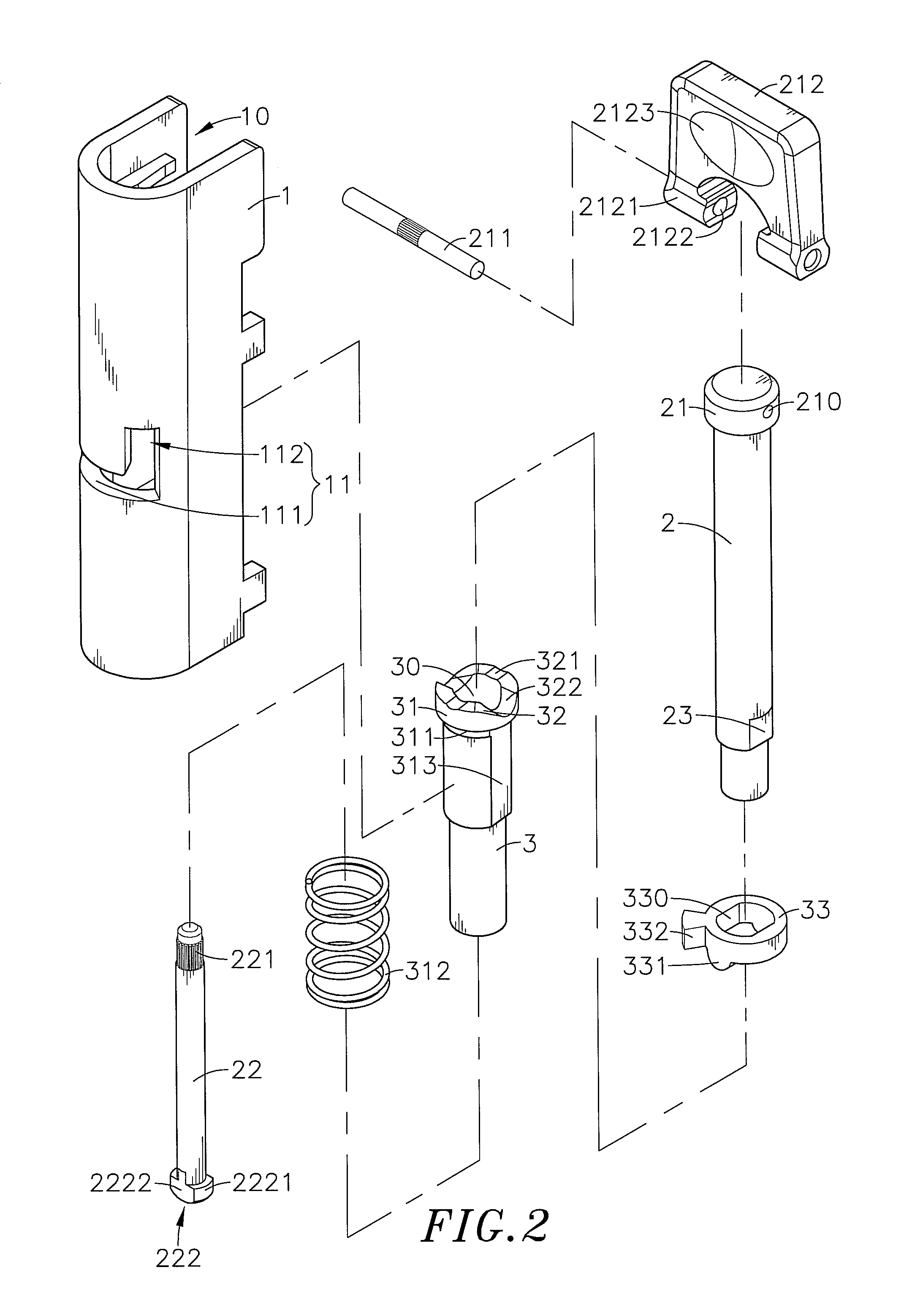
[0026]Referring to FIGS. 1, 2 and 3, a panel member locking device in accordance with the present invention is shown. The panel member locking device comprises a bracket 1, a driving rod 2, a locking rod 22, a pivot pin 211, a flat swivel grip 212, a guide tube 3, a spring member 312, and a constraint member 33.

[0027]The bracket 1 comprises a longitudinal sliding space 10, an L-shaped limiter slot 11 cut through the peripheral wall thereof in communication with the longitudinal sliding space 10 and dividing the longitudinal sliding space 10 into an upper sliding space 101 and a lower sliding space 102, a shoulder 103 located on the inside wall thereof corresponding to the connection area between the upper sliding space 101 and the lower sliding space 102, a mounting flange 12 perpendicularly extended from one lateral side thereof, and a plurality of mounting through holes 120 located on the mounting flange 12 at different elevations for the mounting of screws 121 respectively. Furth...


PUM


Abstract

A panel member locking device includes a bracket affixed to a frame shell, a driving rod vertically movably set in the bracket, a locking rod connected to the driving rod and vertically movable by the driving rod into a through hole at a first panel member and an oblong locating hole at a second panel member and rotatable by the driving rod between a locking position to lock the first and second panel members to the frame shell and an unlocking position to unlock the first and second panel members from the frame shell, a guide tube axially movably set in the bracket to guide the driving rod to move axially and rotate relative to the bracket, a spring member to impart an upward pressure to the guide tube, and a constraint member coupled between the driving rod and the bracket to limit the rotation angle of the driving rod.

Description

BACKGROUND OF THE INVENTION[0001]1. Field of the Invention[0002]The present invention relates to fastener means for joining a frame shell and two panel members and more particularly, to a panel member locking device, which comprises a bracket affixed to a frame shell, a driving rod, a guide tube for guiding the driving rod to move axially up and down relative to the bracket, a constraint member coupled between the driving rod and the bracket for guiding the driving rod to rotate relative to the bracket, a spring member sleeved onto the guide tube and stopped between a head block of the guide tube and a shoulder inside the bracket, and a locking rod connected to the bottom end of the driving rod and movable and rotatable by the driving rod for detachably locking two stacked panel members at the frame shell.[0003]2. Description of the Related Art[0004]When joining panel members, fastening devices respectively formed of a screw nail, a rotary knob and a washer may be used. During appli...

Claims


Application Information

Patent Timeline
IPC IPC(8): F16B21/04
CPCF16B5/10Y10T403/599Y10T403/602Y10T403/7007F16B2200/205F16B5/0092
Inventor TSENG, YING-CHIH
Owner HANWIT PRECISION IND LTD
Learn More