Turboprop engine with compressor turbine shroud

a compressor turbine and turbine technology, applied in the direction of machines/engines, efficient propulsion technologies, manufacturing tools, etc., can solve the problems of air leakage, deflection of such support components, and limited tip clearan

Active Publication Date: 2014-03-13
PRATT & WHITNEY CANADA CORP
View PDF17 Cites 21 Cited by
  • Summary
  • Abstract
  • Description
  • Claims
  • Application Information

AI Technical Summary

Problems solved by technology

The propeller loads can thus potentially cause deflections of such support components.
However, air leakage may occur, for example between the shroud and the adjacent turbine support case supporting ot...

Method used


Image

  • Turboprop engine with compressor turbine shroud
  • Turboprop engine with compressor turbine shroud
  • Turboprop engine with compressor turbine shroud

Examples


Embodiment Construction

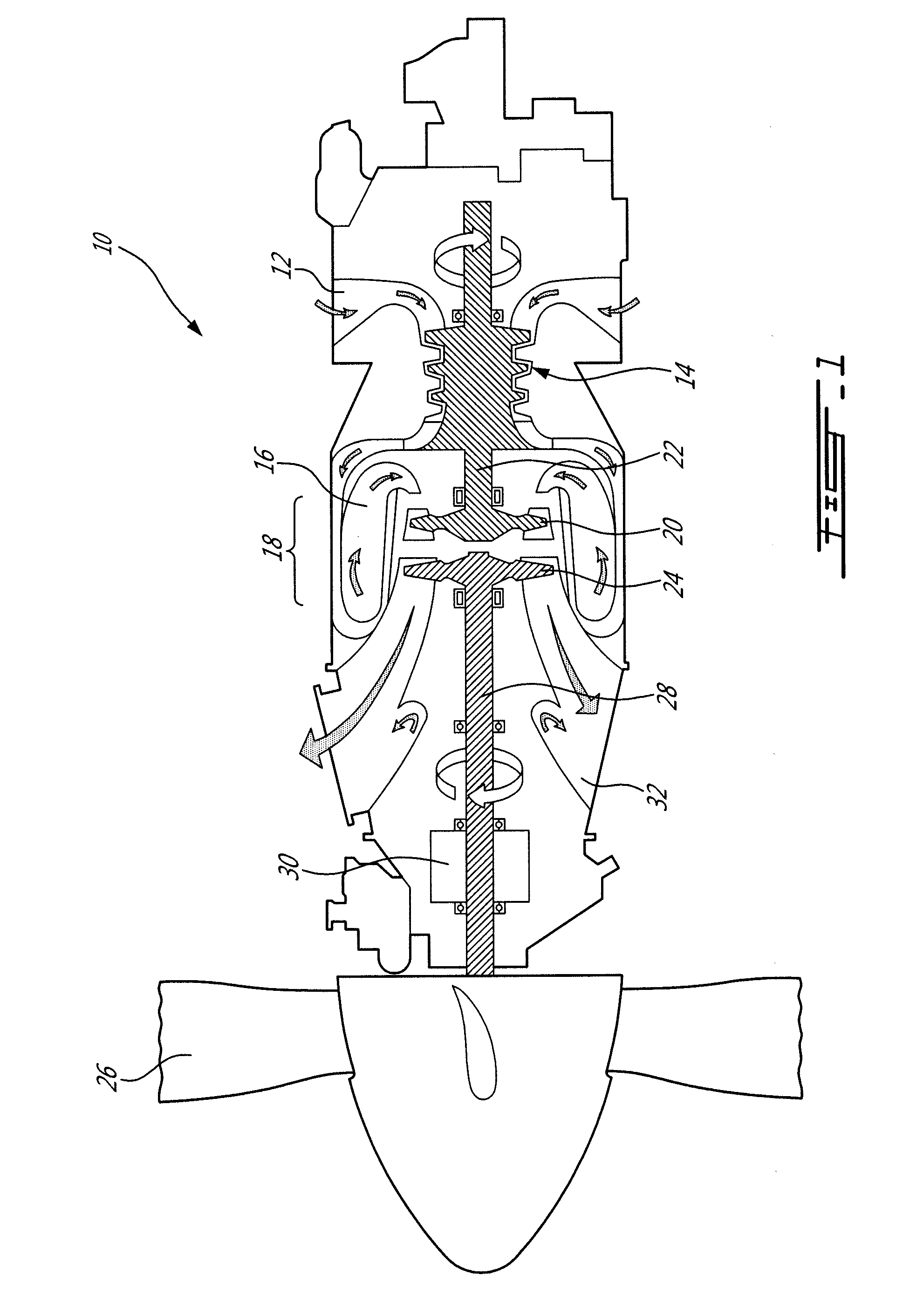
[0012]FIG. 1 illustrates a gas turbine engine 10 of a type preferably provided for use in subsonic flight, generally comprising in serial flow communication an air inlet 12 through which ambient air enters the engine, a compressor section 14 for pressurizing the air, a combustor 16 in which the compressed air is mixed with fuel and ignited for generating an annular stream of hot combustion gases, and a turbine section 18 for extracting energy from the combustion gases. The turbine section 18 includes a compressor turbine section 20 driving the rotor(s) of the compressor section 14 through a compressor shaft 22, and a free power turbine section 24 driving a propeller 26 through a power shaft 28 and an appropriate type of gearbox 30.

[0013]In the present specification, including the claims, the terms “upstream” and “downstream” are defined with reference to the general direction of the airflow between the engine inlet 12 and engine outlet 32; as such, an element “upstream” of another i...


PUM

PropertyMeasurementUnit
Pressureaaaaaaaaaa
Perimeteraaaaaaaaaa

Abstract

A turboprop engine including an annular outer case including a mount ring for attachment to an aircraft along a plane to transfer loads from a propeller and having an annular flange extending radially inwardly therefrom within the plane, an annular turbine support case received within the outer case and connected to the outer case only through a direct connection with the annular flange allowing a limited relative pivoting motion between the turbine support case and the mount ring, and a turbine section including a rotor closely surrounded by a shroud with an annular tip clearance being defined therebetween, the shroud being directly connected to and located by the turbine support case. A method of isolating a turbine shroud from propeller loads in a propeller engine is also disclosed.

Description

TECHNICAL FIELD[0001]The application relates generally to gas turbine engines and, more particularly, to turboprop engines having a compressor turbine shroud.BACKGROUND OF THE ART[0002]Engine mounts provide for the transfer of engine thrust to the aircraft, but the first engine mount, or in a case of a single plane mount engine, the single plane mount, also generally transfers loads onto the gas turbine engine during operation. The engine includes various support components which are directly or indirectly connected to the first mount or single plane mount and to the engine core, defining various load paths for transmission of propeller loads from the mount. The propeller loads can thus potentially cause deflections of such support components.[0003]The high pressure turbine rotor located at the exit of the combustor is usually surrounded by a shroud on which cooling air is circulated, for example through impingement cooling. A tight tip clearance must generally be maintained between...

Claims


Application Information

Patent Timeline
IPC IPC(8): F02C7/20B23P11/00
CPCF01D25/246F02C6/206F05D2230/642F05D2250/411Y10T29/49236F01D11/08Y02T50/60B64D27/10F02C3/10F02C7/20
Inventor MACFARLANE, IAN ALEXANDER
Owner PRATT & WHITNEY CANADA CORP
Why Eureka
Try Eureka