
Trim for input/output architecture in an electronic device

Inactive Publication Date: 2014-03-13
APPLE INC
View PDF6 Cites 8 Cited by
  • Summary
  • Abstract
  • Description
  • Claims
  • Application Information

AI Technical Summary

Benefits of technology

The present invention provides a system and apparatus for protecting the internal components of electronic devices from damage due to external forces. The invention can be used in various electronic devices such as mobile phones, laptops, or tablets. The invention includes a stainless steel trim that is interposed between the external housing of the device and the internal plug receptacle. The stainless steel trim has an elongate lip that closely fits and engages with an opening on the side wall of the external housing, allowing proper alignment between the trim and the housing. The close fitting elongate opening and the alignment with the internal plug receptacle help guide a plug during plug attachment to ensure proper plug insertion. The stainless steel trim also includes a bracket that fastens the trim to the back portion of the external housing to distribute received forces. The invention helps reduce the risk of moisture penetration to sensitive internal components, is aesthetically appealing, and can protect the device from damage during everyday use.

Problems solved by technology

The close-fitting lip facilitates proper alignment between the trim and the device housing and further limits the ability for moisture to access the sensitive internal components of the device.
Furthermore, the trim may distribute forces to the mobile device side wall.
Absent the stainless steel trim, the forces imparted on the internal plug receptacle may damage the receptacle and other attached internal components.
This embodiment also limits the chances of moisture penetration to the sensitive internal components of the electronic device.

Method used


Image

  • Trim for input/output architecture in an electronic device
  • Trim for input/output architecture in an electronic device
  • Trim for input/output architecture in an electronic device

Examples


Embodiment Construction

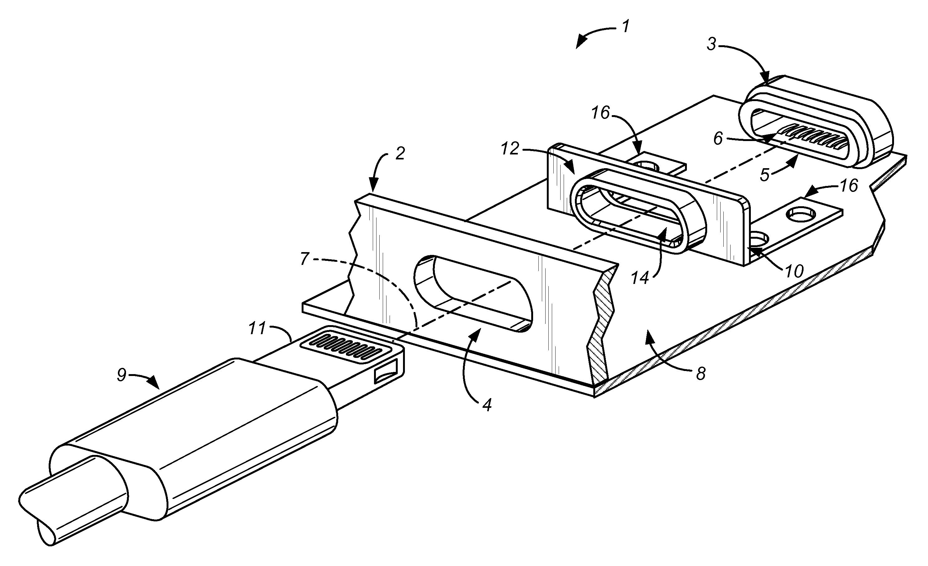
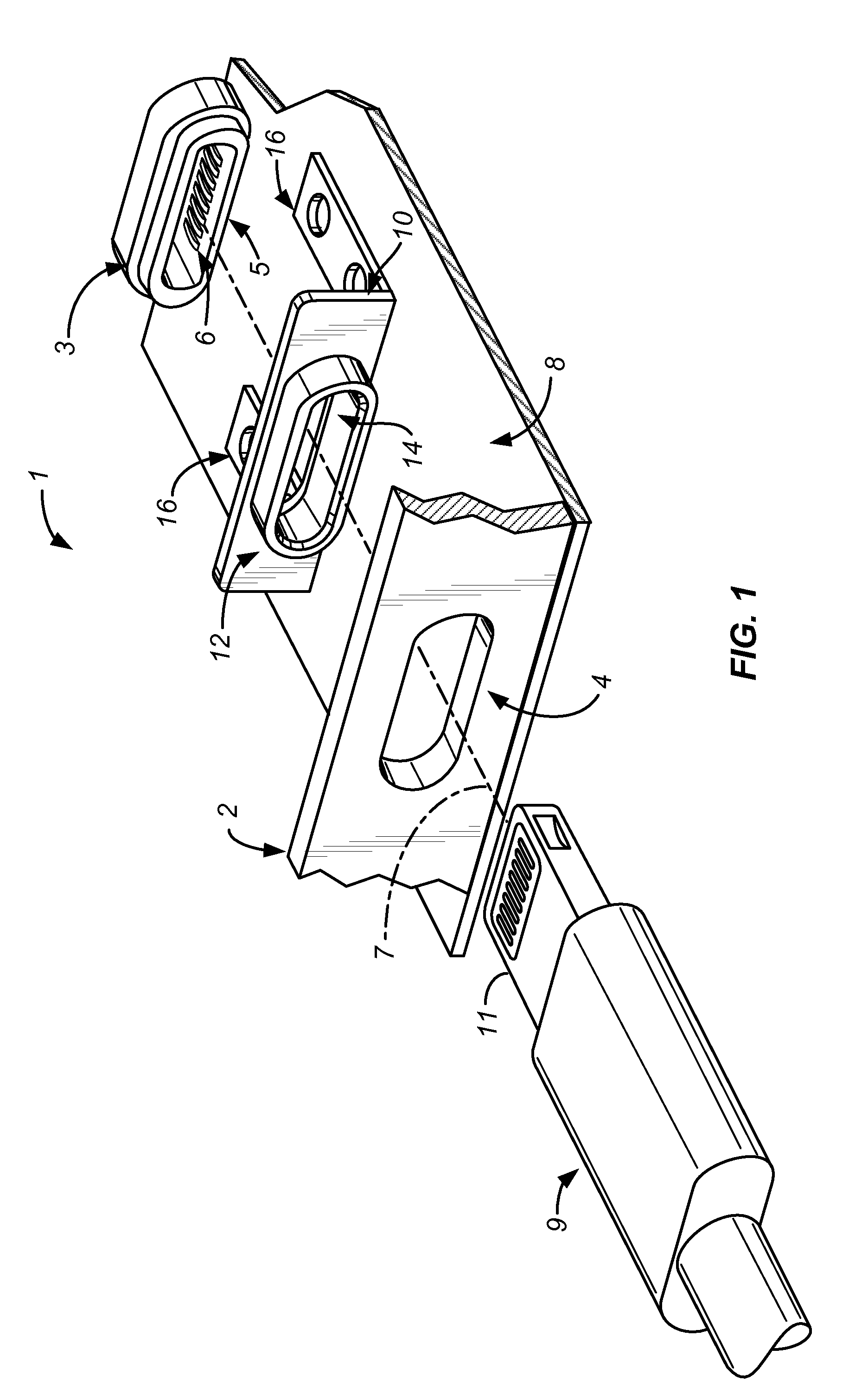
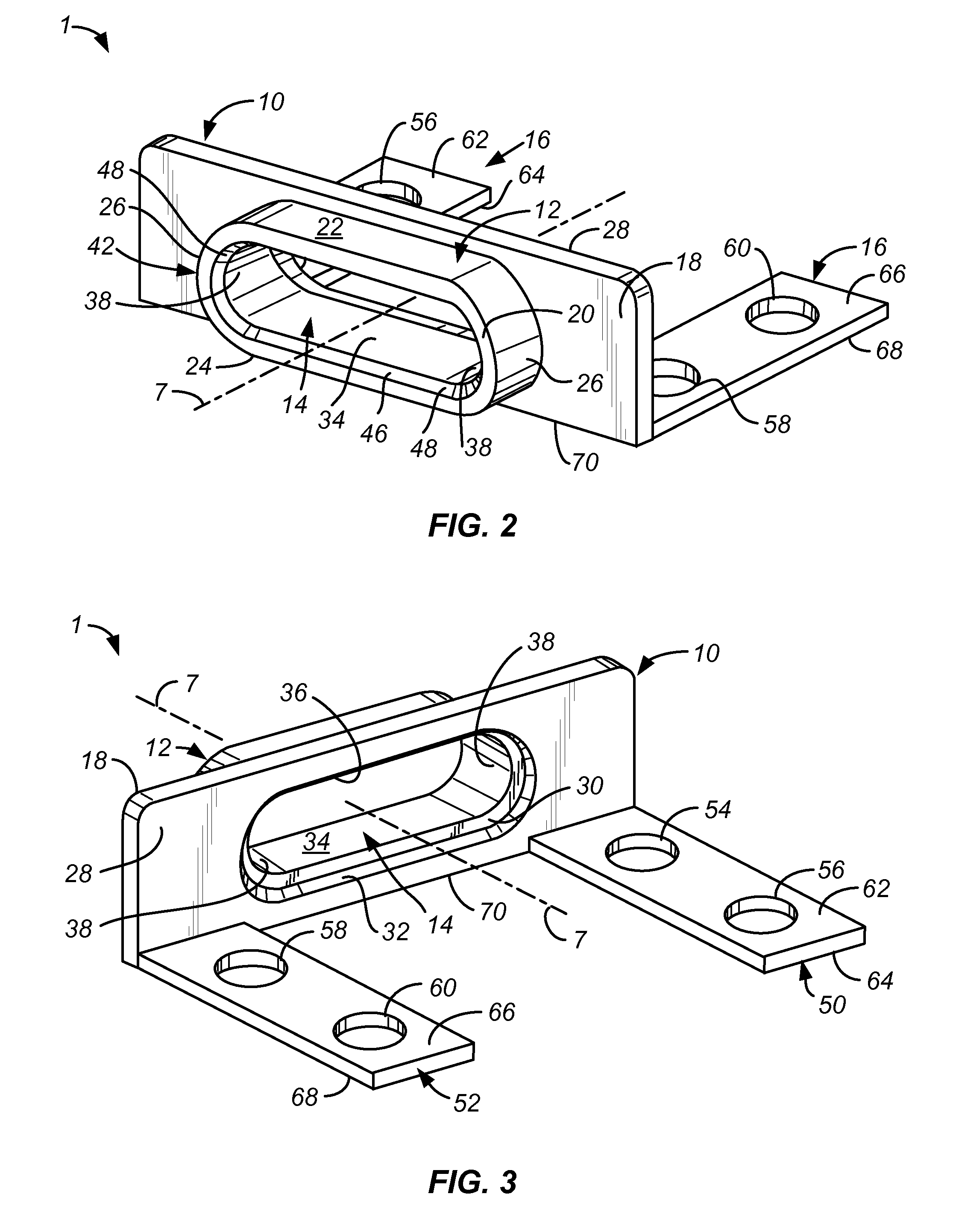
[0027]FIG. 1 illustrates an exploded view of trim 1 according to an exemplary embodiment of the invention. It shows the operational assembly of exemplary trim 1 with corresponding side housing 2, corresponding back housing 8, corresponding plug receptacle 3, and corresponding plug 9. Broadly, trim 1 includes trim body 10, lip 12, trim opening 14 and bracket 16. Lip 12 of trim 1 closely fits and cooperates with housing opening 4 of side housing 2. Similarly the walls of trim opening 14 closely fit and cooperate with the outer walls of connector 11 of plug 9. Bracket 16 fastens trim 1 to back housing 8. Plug receptacle 3 has engagement feature 5 which attaches to a corresponding engagement feature on the back surface of trim 1. The corresponding engagement feature can be more easily seen in FIG. 3 of the present application. Connector 11 translates along plug insertion axis 7 through housing opening 4 and trim opening 14 to attach to and detach from plug receiver 6. Plug insertion axi...


PUM


Abstract

A trim is provided which may be substantially concealed in an electronic device housing. Embodiments may be configured to distribute received forces away from internal components of an electronic device. Further some embodiments may be configured to align an electronic device housing with the internal plug receptacle for ease of assembly. Some embodiments may be configured to align a plug with the plug receptacle during plug attachment to ensure the correct attachment of the plug. Further embodiments may be made of a substantially rigid material to sustain repeated cycles plug insertion and removal. Additional embodiments may limit the ability for moisture to access the internal components of the electronic device. Certain embodiments may be interposed between a plug receptacle and an electronic device housing.

Description

CROSS REFERENCE TO RELATED APPLICATIONS[0001]This application is a non-provisional, claiming benefit under 35 U.S.C. §119(e), of U.S. Patent Application No. 61 / 699,691 filed Sep. 11, 2012 for “Trim For Input / Output Architecture In An Electronic Device”. The entire disclosure of the above mentioned application is incorporated by reference for all purposes.BACKGROUND OF THE DISCLOSURE[0002]Electronic devices have exponentially increased in complexity and capability over the past couple of decades. There is an ongoing push to increase electronic device capabilities and the possibilities are endless. For example, mobile phones are now able to browse the internet, download multimedia, and act as an electronic wallet, a GPS device, and a digital camera. A somewhat conflicting interest is to maintain a reasonable size for electronic devices. For example a mobile device becomes a lot less “mobile” if it becomes too bulky. Thus, one option has been to continually reduce the size of electroni...

Claims


Application Information

Patent Timeline
IPC IPC(8): H02G3/22
CPCH02G3/22H01R13/516H01R13/5202H04M1/0274
Inventor MONTEVIRGEN, ANTHONY S.SANFORD, EMERY A.JENKS, KENNETH A.SHEDLETSKY, ANNA K.DE IULIIS, DANIELE
Owner APPLE INC
Learn More