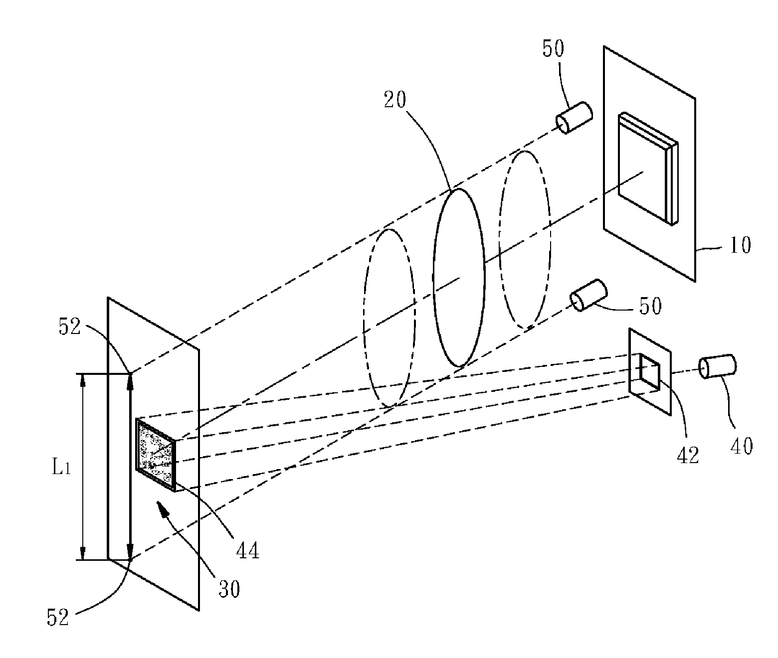
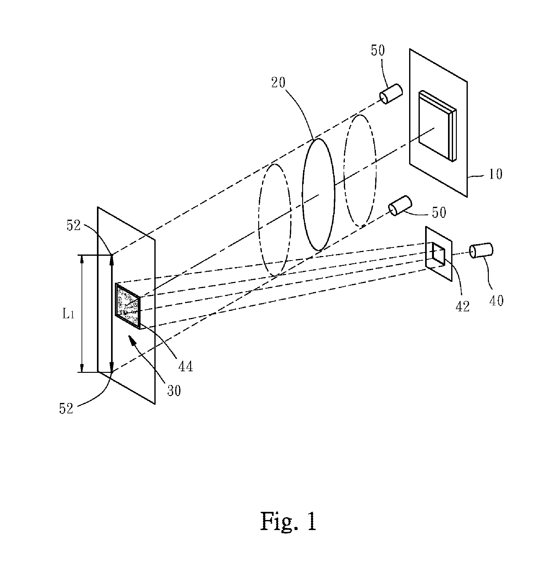
[0024]Referring to FIGS. 1, 2, 3 and 4, a preferred embodiment of the invention provides a barcode reading method and a barcode reading device. The barcode reading method includes the steps as follow.
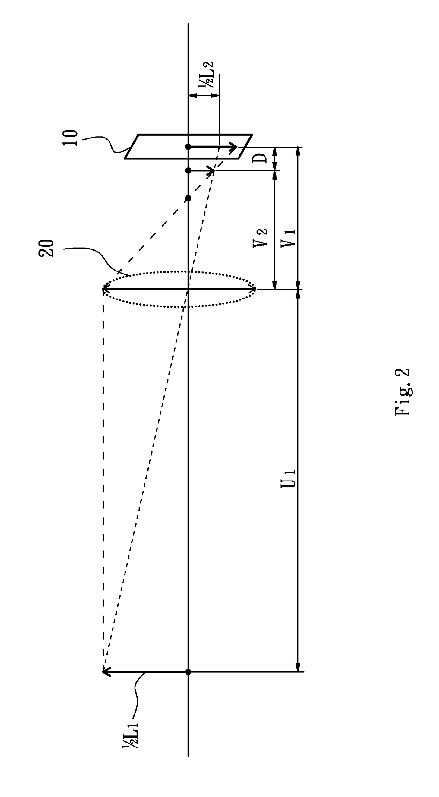
[0025]Firstly, in a capturing step of an image of a barcode, an image sensor 10 is utilized to capture an image of a barcode 30 via an optical lens 20, in which the optical lens 20 itself is provided with an optical focal distance, and an initial image distance V1 is provided between the image sensor 10 and the optical lens 20.
[0026]In the process of capturing the image of the barcode 30, a light source 40 is utilized to project a lighting frame 44 toward the barcode 30 via a frame body 42 so that the image sensor 10 can be correctly aligned with the barcode 30. In this preferred embodiment, the light source 40 is a light-emitting diode. The lighting frame 44 is located at the middle of the barcode 30. The light source 40 and the image of the barcode 30 are distinguishable so that the image sensor 10 can capture the image of the barcode 30 by the assist of the lighting frame 44, and then the data of a digital image of the barcode 30 can be produced.
[0027]Further, two light sources 50 that are located at the same side of the image sensor 10 are utilized to vertically project two calibration images 52 toward the barcode 30, and each of the two light sources 50 is distinguishable from the image of the barcode 30. In this preferred embodiment, the light sources 50 are laser diodes. The two calibration images 52 are spaced a first distance L1, so that the two calibration images 52 are spaced a second distance L2 in the data content of the digital image of the barcode 30 captured by the image sensor 10. The first distance L1 can be a vertical distance as mentioned above, or a horizontal distance.
[0028]Secondly, in a calculating step of the digital image, when the digital image of the barcode 30 is captured by the image sensor 10, the data of the digital image is calculated and decoded by a microcontroller 60 that is electrically connected to the image sensor 10, collocating with a triangulation method and an ideal lens imagining method. The triangulation method applied by the invention is expressed as the following equation (A), wherein an actual object distance U1 is obtained from the first distance L1 divided by the second distance L2 and then multiplied by the initial image distance V1.
U1=(L1/L2)*V1 (A)
[0029]The ideal lens imagining method applied by the invention is expressed as the following equation (B), wherein a reciprocal of an optimum image distance V2 is obtained by subtracting a reciprocal of the actual object distance U1 from a reciprocal of a focal distance f of the optical lens 20.
1 V 2 = 1 f - 1 U 1 ( B )
[0030]A travel distance D of the image of the barcode 30 can be obtained by calculating the difference between the initial image distance V1 and the optimum image distance V2.
[0031]Thirdly, in an adjusting image distance step, a moving device 70 is utilized to change a distance between the optical lens 20 and the image sensor 10. As shown in FIG. 3, the optical lens 20 can be moved at the travel distance in the above-described calculating step by the moving device 70 to reimage the barcode 30 on the image sensor 10, so that a clear digitalized barcode image can be produced by the image sensor 10. In the moving device 70 of this preferred embodiment, a step motor 72 is utilized to drive the optical lens 20 disposed on a rail assembly 74. The moving device 70 is electrically connected to the microcontroller 60. The microcontroller 60 controls the moving device 70 to move the optical lens 20 with respect to the image sensor 10 at the travel distance D. Alternatively, moving the image sensor 10 can attain the same purpose of the invention.
[0032]In the above-described method, the calculating step is utilized to decode the digital image of the barcode 30, adjusting the optical lens 20 to a position capable of forming clear image, regardless of the distances between the barcode 30, the image sensor 10, and the optical lens 20. FIG. 5 is a schematic view showing optimum detection ranges of barcodes with various formats. From FIG. 5, it is understood that the optimum detection distance between the barcode and the image sensor is varied, depending on the formats of barcodes. Similarly, the optimum range of the positions of the barcode and image sensor depends on the formats of barcodes. Accordingly, with the adjustable distance between the optical lens 20 and the barcode 30 of the invention, the image sensor can clearly and accurately capture the barcodes of various formats, thereby providing automatic focusing adjustment and allowing the invention to be extensively applied in different fields.
[0033]Moreover, by using the method of capturing and calculating the digital image data of the barcode to perform the focusing function, operations such as decoding and controlling of focus can be completely executed by software so that image focusing process can be more convenient and immediate, and users do not have to visually inspect the barcode so that focusing effect can be more accurate and clear.
[0034]While this invention has been described in connection with what is presently considered to be the most practical and preferred embodiment, it is to be understood that the invention is not limited to the disclosed embodiments, but, on the contrary, is intended to cover various modifications and equivalent arrangements included within the spirit and scope of the appended claims.