
Structure of Stereo Optical Engine for Projection

a stereo optical engine and engine technology, applied in the direction of projectors, polarising elements, instruments, etc., can solve the problems of inability to achieve various aspects, heavy device for driving the shutter, high price, etc., and achieve the effect of accurate and clear images, low cost, and reduced cos

Inactive Publication Date: 2009-07-02
REDROVER
View PDF6 Cites 4 Cited by
  • Summary
  • Abstract
  • Description
  • Claims
  • Application Information

AI Technical Summary

Benefits of technology

[0014]In accordance with the stereo optical engine according to the present invention, a light beam emitted from light sources 1,3 has its direction shifted through a prism 5, a mirror 9, a first polarization beam splitter 11, DLPs 21, 23, and a second polarization beam splitter 29, and is then generated as one stereo image. Accordingly, there are advantages in that accurate and clear images can be obtained by controlling a setting state simply, if necessary, and a projection stereo image combiner can be implemented cheaply compared with a case where two projectors are moved.
[0015]Further, in the present invention, images combined by the second polarization beam splitter 29 have the same optical axes, and only one projection lens is used. Accordingly, there are advantages in that additional alignment is not required, and alignment of an optical axis depending on a projection length is unnecessary.
[0016]In addition, there are advantages in that zoom magnification or focusing between two lenses needs not to be set identically since zoom or focusing is performed by one lens, and cost, volume and / or weight can be decreased since the entire optical system is integrated into one without using two optical systems as in the prior art.

Problems solved by technology

However, the method of projecting an image by using one projector and combining the image in a three-dimensional manner by using the shutter glass is advantageous in that an apparatus thereof is cheap, a construction is simple, and a weight is light, but is problematic in that it is not practical in various aspects.
As a result, a device for driving the shutter becomes heavy.
Thus, it is difficult to use the shutter glass equipped with this heavy shutter for a long time, and a severe flicking phenomenon occurs due to the operation of the shutter, thereby causing vertigo.
However, in this conventional stereo image combination method, the price is high because two projectors are used.
There was a problem in that the volume is increased since two projectors must be stacked leftwardly and rightwardly or upwardly and downwardly.
In particular, the above conventional apparatus was disadvantageous in that a setting task for accurately focusing an image must be performed individually according to the situation of a place in case where the apparatus is temporarily installed at a place requiring projection, and was problematic in that alignment is easily twisted due to external shock.
However, there was a problem in that alignment must be performed again by employing lens shift if a projection length increases or decreases even though alignment is completed.
Accordingly, there was a problem in that the linear polarization filter has great loss of light transmittance.

Method used


Image

  • Structure of Stereo Optical Engine for Projection
  • Structure of Stereo Optical Engine for Projection

Examples


Embodiment Construction

[0032]The present invention will now be described in detail with reference to the accompanying drawings.

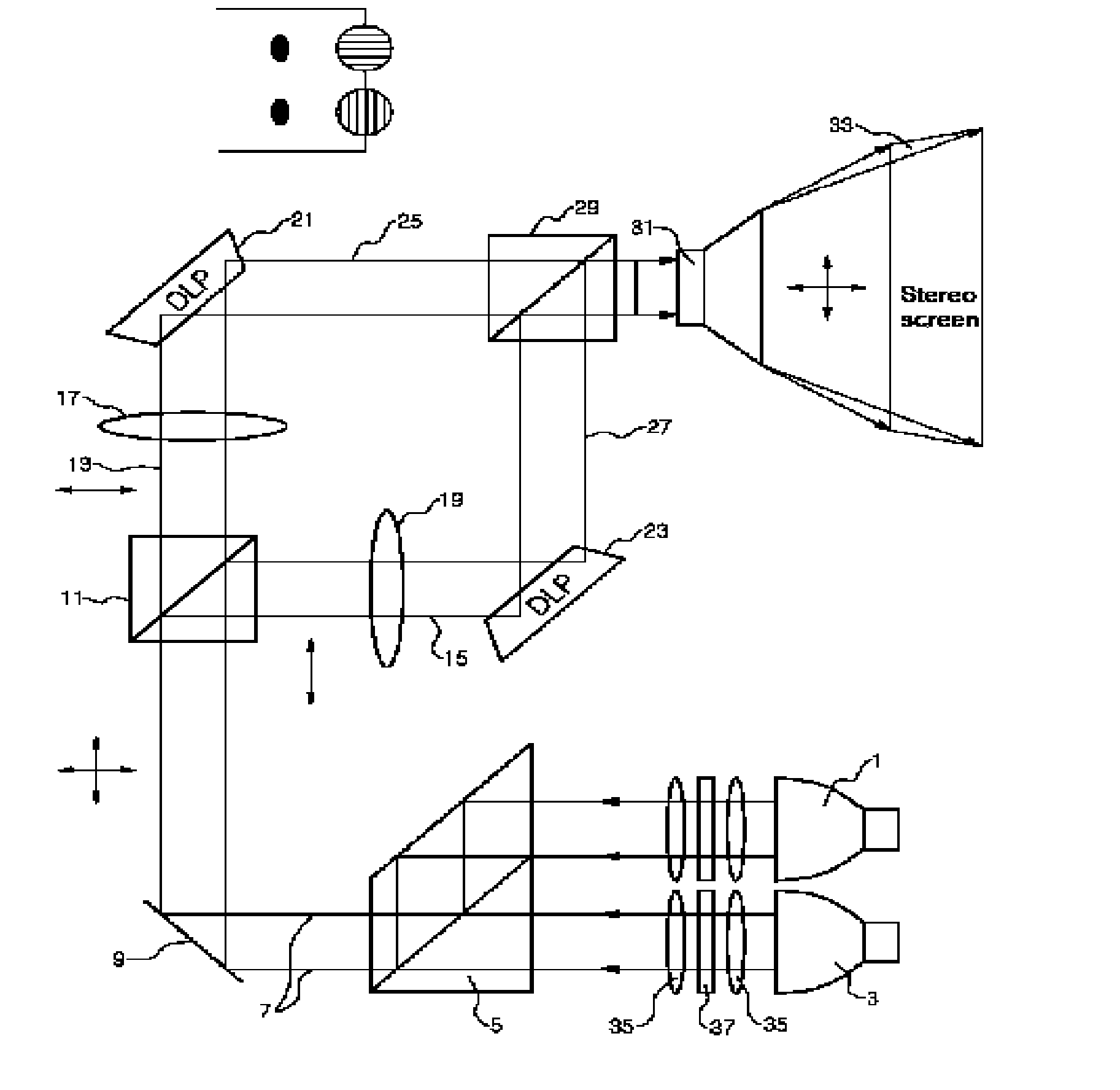
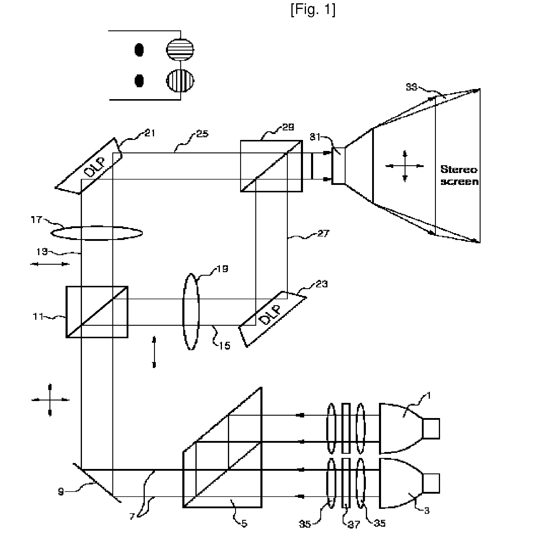
[0033]FIG. 1 is a conceptual view illustrating a stereo optical engine structure for projection according to the present invention. As shown in the drawing, in the stereo optical engine structure according to the present invention, two light beams emitted from two light sources 1,3 are gathered into one light beam 7 through a prism 5. The collected light beam 7, which has passed through the prism 5, is reflected from a mirror 9 and then bisected at a first polarization beam splitter 11. A light beam 13 whose polarization direction is horizontal is transmitted, and a light beam 15 whose polarization direction is vertical is reflected and has its direction shifted. The horizontally and vertically polarized light beams 13,15, which are separated from the first polarization beam splitter 11, are transferred to left and right DLPs 21,23, respectively, through color wheels 17,19 for cor...


PUM


Abstract

The present invention relates to a stereo optical engine structure for projection, and more particularly, to a stereo optical engine structure for projection for combining two images to project one stereo image. The present invention discloses a stereo optical engine structure for projection, comprising: a first polarization beam splitter 11 for allowing a horizontally polarized light beam to be transmitted thereto and a vertically polarized light beam to be reflected therefrom among light beams emitted from light sources; color wheels 17,19 for correcting and combining the respective colors of the horizontally polarized light beam and the vertically polarized light beam which are separated from the first polarization beam splitter 11; left and right DLPs 21,23 for receiving the horizontally polarized light beam 13 and the vertically polarized light beam 15 which have passed through the color wheels 17,19, respectively, from the first polarization beam splitter 11 and projecting a horizontally polarized image and a vertically polarized image therefrom; a second polarization beam splitter 29 for combining the horizontally polarized image 25 and the vertically polarized image 27 projected from the left and right DLPs 21,23, respectively, into one stereo image; and a lens 31 for allowing the stereo image combined by the second polarization beam splitter to be projected to a stereo screen therethrough.

Description

TECHNICAL FIELD[0001]The present invention relates to a stereo optical engine structure for projection, and more particularly, to a stereo optical engine structure for projection for combining two images to project one stereo image.BACKGROUND ART[0002]In general, in order to view stereo images, a variety of image formers are used. In an existing projection stereo image combiner, one projector is used to project an image. A viewer who wears a shutter glass views the image projected from the projector, so that he or she can view a consecutive and stereo image.[0003]However, the method of projecting an image by using one projector and combining the image in a three-dimensional manner by using the shutter glass is advantageous in that an apparatus thereof is cheap, a construction is simple, and a weight is light, but is problematic in that it is not practical in various aspects.[0004]For example, in order for an image projected from one projector to be recognized as a stereo image, a vi...

Claims


Application Information

Patent Timeline
Patent Type & Authority Applications(United States)
IPC IPC(8): G02B27/18G02B27/26G02B30/25G02B30/60H04N13/363
CPCG02B27/26H04N13/0459H04N13/0427H04N13/363H04N13/365G02B30/25G03B21/00G03B21/14
Inventor KIM, JUNG HOIHA, HOI JIN
Owner REDROVER
Features
  • Generate Ideas
  • Intellectual Property
  • Life Sciences
  • Materials
  • Tech Scout
  • Unparalleled Data Quality
  • Higher Quality Content
  • 60% Fewer Hallucinations
Learn More