Obstacle detection device for vehicle

a detection device and obstacle technology, applied in the direction of measurement devices, vehicle components, instruments, etc., can solve the problems of not disclosing nor suggesting, and the rear wheel of the own vehicle is misdetected as a target vehicle,

Active Publication Date: 2014-03-13
MAZDA MOTOR CORP
View PDF11 Cites 48 Cited by
  • Summary
  • Abstract
  • Description
  • Claims
  • Application Information

AI Technical Summary

Benefits of technology

[0009]The present invention has been made in view of the above problem, and an object thereof is to provide a vehicle obstacle detection device capable of preventing a situation where a wheel of an own vehicle is misdetected as a target.

Problems solved by technology

An error in the discrimination leads to a situation where an object other than the target vehicle is recognized as the target vehicle, and consequently becomes a factor for erroneous alarm or erroneous control.
However, if, as a result, for example, of undergoing reflection by a back surface of the rear bumper, a part of a transmission wave from the radar unit is oriented to pass between a transmitter section of the radar unit and the back surface of the rear bumper and reach a rear wheel of the own vehicle, and then a reflected wave returned from the rear wheel is input into a receiver section of the radar unit, a problem occurs that the rear wheel of the own vehicle is misdetected as a target vehicle although it is not really a target vehicle.
However, this is undesirable from a practical standpoint, because an external impact force added to the bumper due to a mild rear impact collision or the like leads immediately to malfunction and / or damage of the radar.
However, the Patent Document 1 neither discloses nor suggests the aforementioned misdetection.
However, the Patent Document 2 does not disclose a technical problem of how to prevent the misdetection caused by the phenomenon that a part of a transmission wave from a radar unit passes between a transmitter section of the radar unit and a back surface of a bumper and reaches a wheel of an own vehicle, and then a reflected wave is returned from the wheel.

Method used


Image

  • Obstacle detection device for vehicle
  • Obstacle detection device for vehicle
  • Obstacle detection device for vehicle

Examples


first embodiment

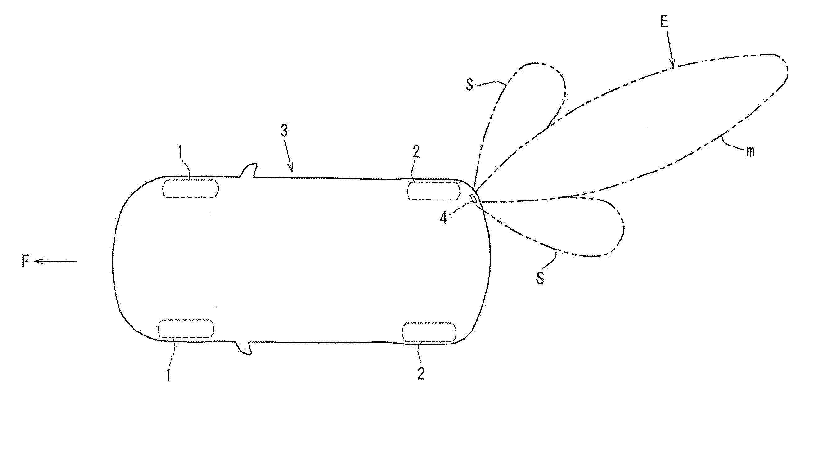
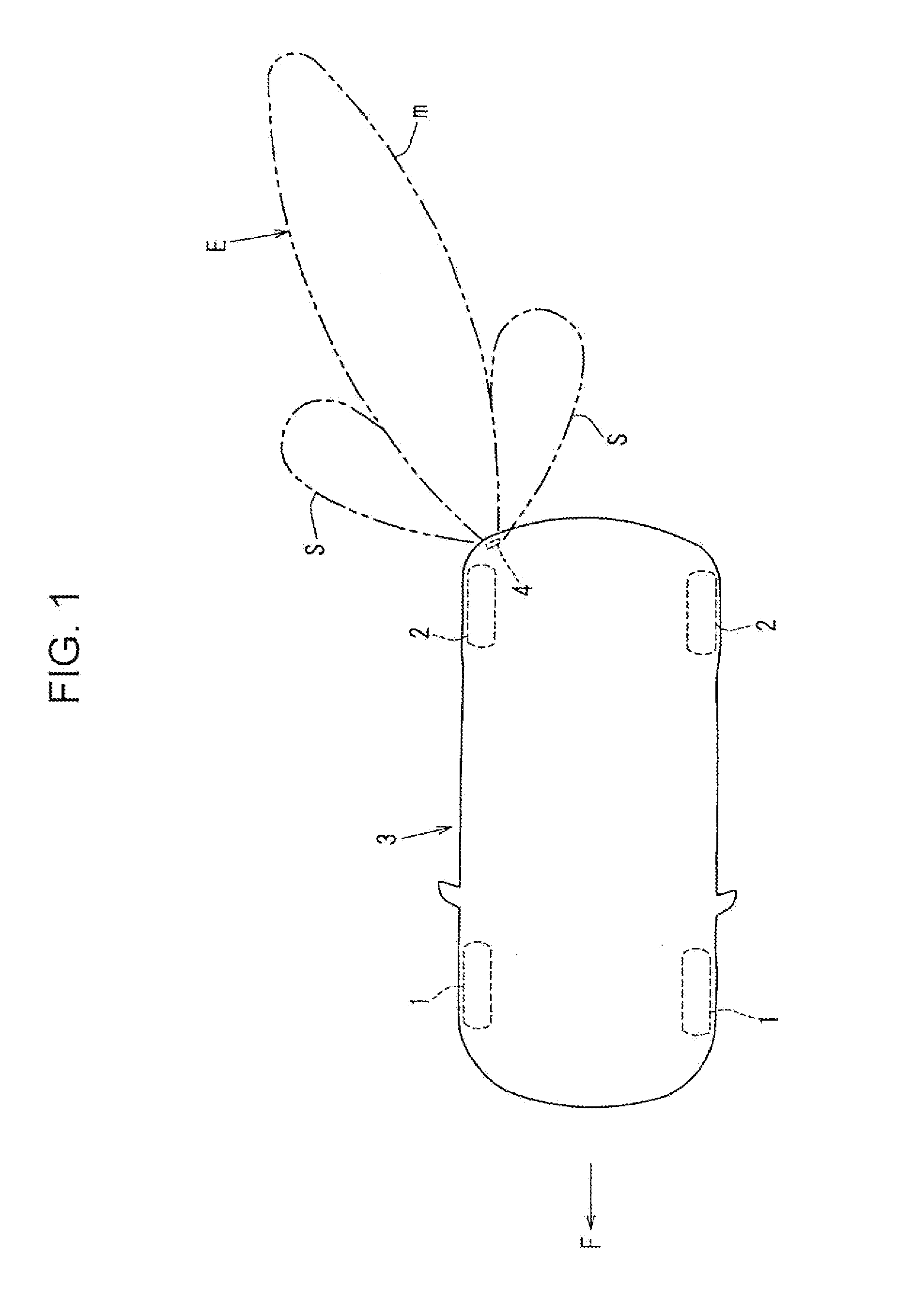
[0037]FIG. 1 is a schematic top plan view illustrating a vehicle equipped with a vehicle obstacle detection device according to the present invention, and an obstacle detection area to be covered by the vehicle obstacle detection device. A radar unit 4 is provided between a back surface of a bumper of a vehicle 3 having front wheels 1, 1 and rear wheels 2, 2, and one 2 of the rear wheels. The radar unit 4 is configured to detect whether or not an obstacle is present. That is, a radio wave emitted from a transmitter-receiver section 4a of the radar unit 4 is transmitted toward an outside of the vehicle, specifically, in a vehicle-rearward and vehicle-widthwise outward direction, through a bumper made of a resin, and, after being reflected by an obstacle, returned to the transmitter-receiver section 4a. In response to receiving the reflected wave, the radar unit 4 detects the presence of an obstacle.

[0038]In FIG. 1, an obstacle detection area of the radar unit 4 is indicated by the co...

second embodiment

[0056]FIG. 4 is a sectional view illustrating a second embodiment for a vehicle obstacle detection device. In this embodiment, a radar unit 4 is attached to a rear end panel 5 in the same manner as that in the first embodiment. Further, the aforementioned shield plate 7 is bonded and fixed to a back surface of a rear bumper 6, in a region where a vehicle-widthwise end of the rear bumper 6 is formed to bend in a vehicle forward direction, and disposed to extend from the fixed position toward the radar unit 4 approximately along a vehicle-widthwise inward direction. Further, the shield plate 7 is provided closer to the radar unit 7 than the reflection point RP where the tire reaching wave α is reflected by the back surface of the rear bumper 6.

[0057]In the second embodiment, a part of a transmission wave emitted from a transmitter-receiver section 4a of the radar unit 4 is oriented to become incident on the shield plate 7 at a position just before the reflection point RP, as indicated...

third embodiment

[0061]FIG. 5 is a sectional view illustrating a third embodiment for a vehicle obstacle detection device. In this embodiment, a radar unit 4 is attached to a rear end panel 5 in the same manner as that in the aforementioned first and second embodiments. Further, in a region where both of opposed vehicle-widthwise ends of the rear end panel 5 and a rear bumper 6 are formed to bend in a vehicle forward direction, a shield plate 7 is provided to extend from the rear end panel 5 toward the rear bumper 6 in a vehicle-widthwise outward and vehicle-rearward direction, and another shield plate 9 is provided to extend from the rear bumper 6 toward the rear end panel 5 in a vehicle-widthwise inward and vehicle-forward direction. A rearward end of the one shield plate 7 is spaced apart from a back surface of the rear bumper 6, and an inward end of the other shield plate 9 is spaced apart from the rear end panel 5.

[0062]Further, the shield plates 7, 9 are disposed in spaced-apart relation to ea...


PUM


Abstract

A vehicle obstacle detection device comprises: a radar unit provided between a back surface of a bumper and a wheel and configured to detect an obstacle by transmitting a radio wave through the bumper; and a misdetection prevention member for preventing misdetection in the radar unit by suppressing the occurrence of an own-vehicle's wheel reaching wave which is a part of a transmission wave and which passes between a transmitter section of the radar unit and the back surface of the bumper and reaches the wheel of the own vehicle.

Description

TECHNICAL FIELD[0001]The present invention relates, to a vehicle obstacle detection device for detecting an obstacle by transmitting a radio wave, from a radar unit provided between a back surface of a bumper and another vehicle component, toward an outside of an own vehicle through the bumper.BACKGROUND ART[0002]Generally, in a vehicle obstacle detection device using a radar, it is extremely important to discriminate between a target vehicle (another vehicle around an own vehicle) as a target object to be detected, and an object other than the target vehicle. An error in the discrimination leads to a situation where an object other than the target vehicle is recognized as the target vehicle, and consequently becomes a factor for erroneous alarm or erroneous control.[0003]For example, a vehicle obstacle detection device for detecting, as an obstacle, another vehicle around an own vehicle is configured to attach a radar unit to a rear end panel in front of a rear bumper, through a br...

Claims


Application Information

Patent Timeline
Patent Type & Authority Applications(United States)
IPC IPC(8): G01S13/93G01S13/931
CPCG01S13/931B60R19/483G01S7/414G01S7/2813G01S2013/93275G01S2013/93271G01S2013/93272
Inventor INADA, TAKAHIROHAMADA, YASUSHITSURUNAGA, MARIENAKAHATA, YOUICHIROHANADA, YOSHITSUGUNISHIDA, FUMIHIKOENDO, YASUYUKI
Owner MAZDA MOTOR CORP
Why Eureka
Try Eureka