Microphone rod, headphone and table microphone
A microphone bar and connecting terminal technology, applied in earpiece/earphone accessories, electrostatic transducer microphones, etc., can solve the problems of high contact failure rate, unreliable use, inconvenient disassembly and assembly, etc., to solve unreliable use, prolong The service life and the effect of preventing wrong connection
- Summary
- Abstract
- Description
- Claims
- Application Information
AI Technical Summary
Problems solved by technology
Method used
Image
Examples
Embodiment 1
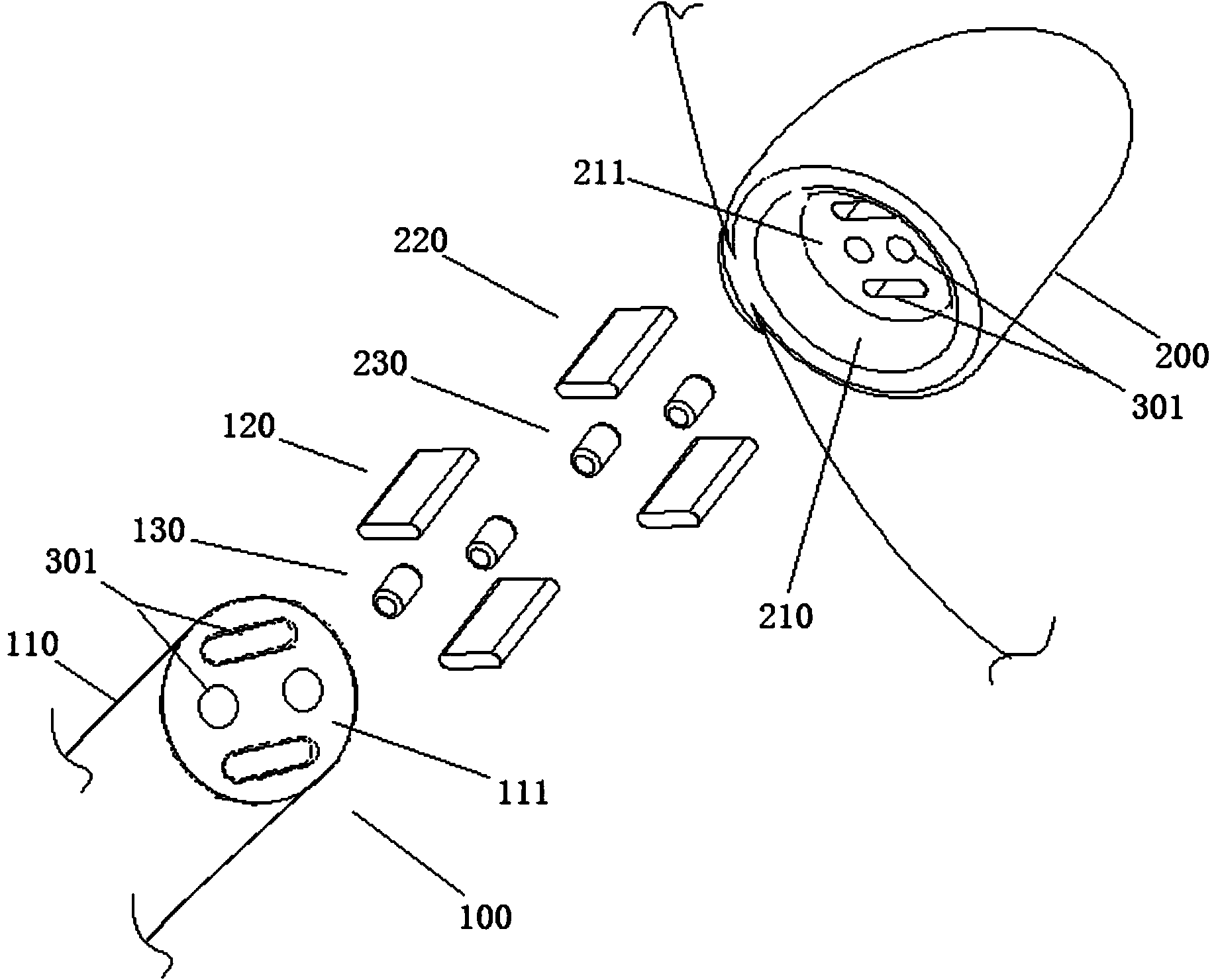
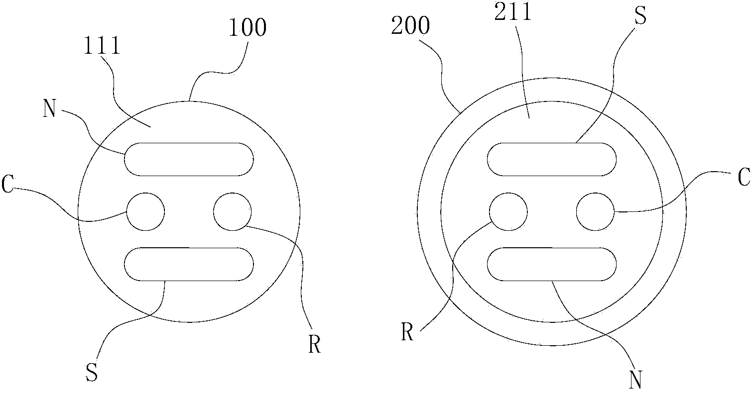
[0027] see figure 1 with figure 2 , a microphone, the microphone includes a microphone body 100 and a microphone seat 200. Microphone base 200 is provided with jack 210, and the bottom 110 of described microphone body 100 can be pulled out in described jack 210, and described jack 210 is used for carrying out radial restriction to inserted described microphone body 100. position; the bottom surface 211 of the insertion hole 210 is provided with a first magnet member 220, the end surface 111 of the bottom end 110 of the microphone body 100 is provided with a second magnet member 120, the first magnet member 220 and the first magnet member 220 The two magnet components 120 are opposite to each other, so that the first magnet component 220 and the second magnet component 120 can be magnetically attracted together, and the axial direction of the microphone body 100 can be fixed.
[0028] The fixing of the microphone body 100 and the microphone base 200 mainly includes radial an...
Embodiment 2
[0033]Specifically, in Embodiment 1, when the microphone body 100 is inserted into the socket 210 of the microphone base 200: it may be that the first connection terminal 230 contacts the second connection terminal 130, and at the same time the first magnet member 220 contacts The second magnet member 120 has the strongest magnetic attraction and the most smooth conduction of the connection terminal in this state, but requires high installation accuracy of the magnet member and the connection terminal to achieve simultaneous contact; it can also be that the first connection terminal 230 contacts The second connection terminal 130, while the first magnet member 220 does not contact the second magnet member 120, the magnetic attraction effect in this state is relatively weak, but the conduction of the connection terminal is still the most smooth, the input terminal R and the output terminal C need to meet the requirements of simultaneous Contact, so the installation accuracy for ...
Embodiment 3
[0037] This embodiment is also an improvement made on the basis of the first embodiment, and the technical content of the first embodiment will not be described again, and the technical content disclosed in the first embodiment also belongs to this embodiment.
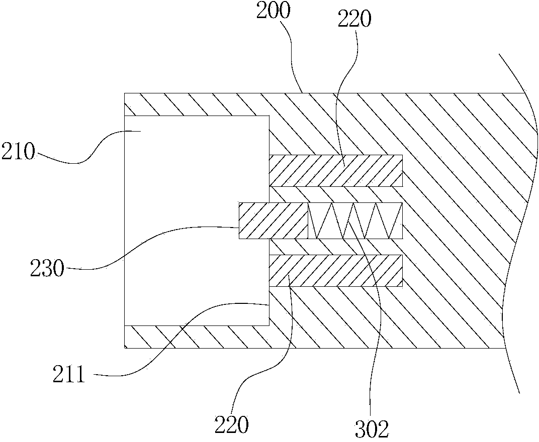
[0038] see Figure 4 The difference between this embodiment and the first embodiment is that the second connection terminal 130 is slidably installed in the corresponding installation hole 301 at the bottom end 110 of the microphone body, and the second connection terminal 130 and the installation hole A compression spring 302 is connected between the bottoms of 301 . Based on the same principle as in Embodiment 2, when the microphone body 100 is inserted into the socket 210 of the microphone holder 200, the first connection terminal 230 contacts the second connection terminal 130 to realize signal conduction, and the first magnet Under the action of the magnetic attraction of the member 220 and the second magnet memb...
PUM
 Abstract
Description
Claims
Application Information
 - R&D
- Intellectual Property
- Life Sciences
- Materials
- Tech Scout
- Unparalleled Data Quality
- Higher Quality Content
- 60% Fewer Hallucinations
Browse by: Latest US Patents, China's latest patents, Technical Efficacy Thesaurus, Application Domain, Technology Topic, Popular Technical Reports.
© 2025 PatSnap. All rights reserved.Legal|Privacy policy|Modern Slavery Act Transparency Statement|Sitemap|About US| Contact US: help@patsnap.com


