Cast-in-situ integral type steel frame filler wall system connected through springs and construction method thereof

A spring connection, steel frame technology, applied in the direction of walls, protective buildings/shelters, building components, etc., can solve the incongruity between the deformation of the steel frame and the infill wall, the poor thermal insulation and earthquake resistance, and the filling of the steel frame. It solves the problems of complicated wall construction and other problems, so as to achieve the effect of saving masonry time and manpower investment, high construction efficiency and reducing construction cost.

Active Publication Date: 2016-10-26
HEBEI INSTITUTE OF ARCHITECTURE AND CIVIL ENGINEERING
View PDF7 Cites 4 Cited by
  • Summary
  • Abstract
  • Description
  • Claims
  • Application Information

AI Technical Summary

Problems solved by technology

[0007] The purpose of the present invention is to provide a spring-connected cast-in-place integrated steel frame filling wall system and its construction method, to solve the technical problems of poor overall performance, poor thermal insulation and earthquake resistance of the existing steel frame filling wall; The problem of uncoordinated deformation of steel frame and infill wall under earthquake action; and solve the problem of complex construction and low efficiency of existing steel frame infill wall

Method used


Image

  • Cast-in-situ integral type steel frame filler wall system connected through springs and construction method thereof
  • Cast-in-situ integral type steel frame filler wall system connected through springs and construction method thereof
  • Cast-in-situ integral type steel frame filler wall system connected through springs and construction method thereof

Examples


Embodiment Construction

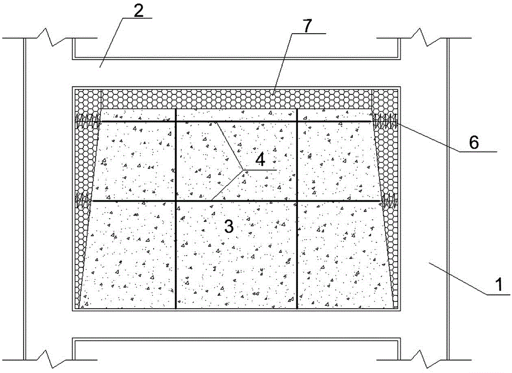
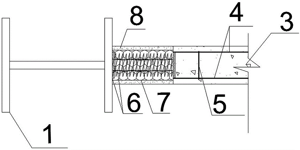
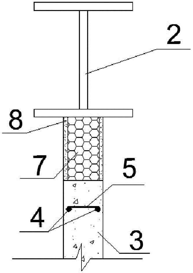
[0057] Examples see Figure 1~4 As shown, this spring-connected cast-in-place integral steel frame filled wall system includes a rectangular frame composed of frame beams 2 and frame columns 1 and a cast-in-place filled wall 3 poured in the rectangular frame. The filling wall 3 is a trapezoid with a narrow top and a wide bottom. The distance between the bottom of the wall and the frame column 1 is 20mm, the distance between the top and the frame column 1 is 70mm, and the distance from the frame beam is 50mm. The cast-in-place filling wall 3 and the Flame retardant flexible filling materials 7 are filled between the frame columns 1 on both sides and the frame beams 2 above.

[0058] The cast-in-place filling wall 3 is an exterior wall located on the periphery of a building or an interior wall located inside a building. When the filling wall is an exterior wall, the wall concrete is light aggregate concrete with heat preservation function, including pumice concrete, foam Concrete...


PUM


Abstract

Disclosed are a cast-in-situ integral type steel frame filler wall system connected through springs and a construction method thereof. The system comprises a rectangular frame and a cast-in-situ filler wall body, wherein the rectangular frame is defined by a frame beam and frame columns in an enclosed mode, and the cast-in-situ filler wall body is cast in the rectangular frame. Elastic devices are connected between the left and right sides of the cast-in-situ filler wall body and the frame columns. The space between the upper side, left side and right side of the cast-in-situ filler wall body and the adjacent frame beam and frame columns is filled with anti-flaming flexible filler materials. By the adoption of a flexible connection mode, relative displacement and corners between the rectangular frame and the filler wall body are allowed, and a cast-in-situ integral type filler wall is obtained, is high in construction efficiency and good in integral performance, lowers labor intensity and has a good anti-seismic property as the first seismic fortification line. As for construction, a cast-in-place concrete construction mode is adopted, so that construction time and manpower input are saved, construction efficiency is improved, and construction cost is reduced. The cast-in-situ integral type steel frame filler wall system connected through the springs and the construction method thereof can be widely applied to steel frame filler wall construction.

Description

technical field [0001] The invention relates to the field of construction engineering, in particular to a filling wall system and a construction method thereof. Background technique [0002] At present, some small hollow blocks or perforated bricks are usually used for building frame-filled walls, which are connected with the main structure through a certain number of tension bars, but this structure has certain defects. [0003] In terms of structural mechanical performance, due to the quality of the masonry, the overall performance of the infill wall is poor. Under the action of earthquakes, the infill wall is prone to slip damage of the masonry mortar layer. At the same time, the masonry mortar is prone to shrinkage during the air-drying process, causing the filling wall to settle and separate from the frame beam, resulting in cracks. [0004] From the perspective of construction, the masonry of blocks or bricks is time-consuming and laborious, which increases labor cost...

Claims


Application Information

Patent Timeline
Patent Type & Authority Applications(China)
IPC IPC(8): E04B2/84E04H9/02E04B1/98
CPCE04B2/84E04H9/021
Inventor 麻建锁周苗苗蔡焕琴白润山麻海栋
Owner HEBEI INSTITUTE OF ARCHITECTURE AND CIVIL ENGINEERING
Why Eureka
Try Eureka