Scanning optical apparatus and image forming apparatus

Active Publication Date: 2014-03-13
BROTHER KOGYO KK
View PDF1 Cites 0 Cited by
  • Summary
  • Abstract
  • Description
  • Claims
  • Application Information

AI Technical Summary

Benefits of technology

The invention is about improving the performance of a scanning optical apparatus by reducing the curvature of field and forming a clear image on the target surface. The inventors conducted a thorough study and found that even if there is a sag in the image, the optical properties can still be improved. This patent aims to provide a solution to these technical problems.

Problems solved by technology

The sag would be a cause of curvature of field or other kind of degradation of images on the target surface to be scanned.

Method used


Image

  • Scanning optical apparatus and image forming apparatus
  • Scanning optical apparatus and image forming apparatus
  • Scanning optical apparatus and image forming apparatus

Examples


examples

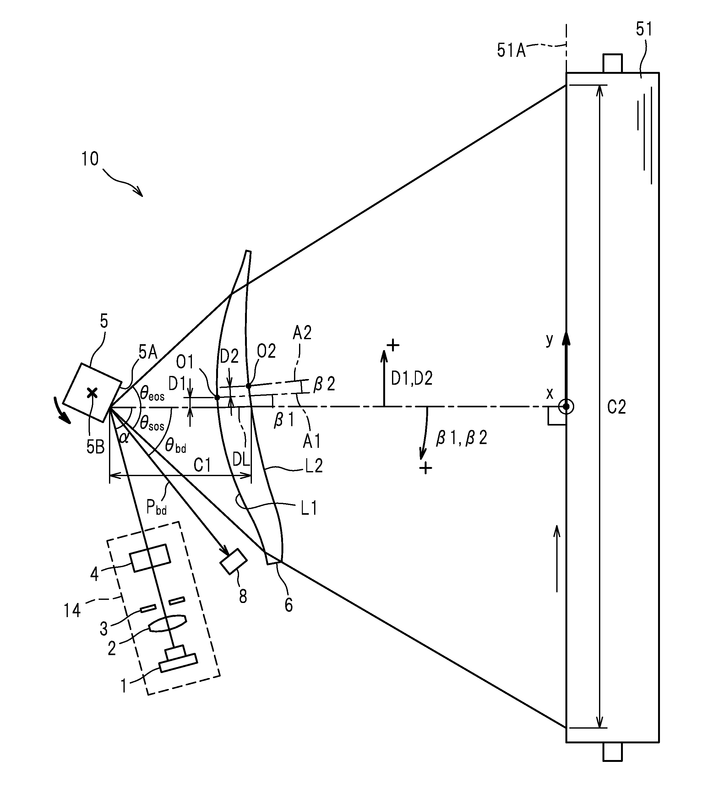
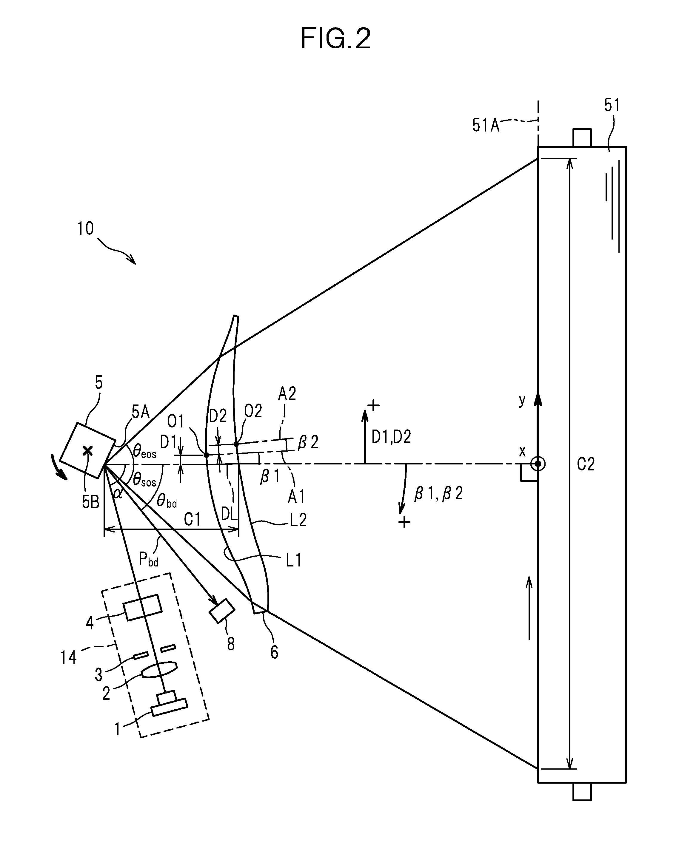
[0046]The following examples describe the ranges of the shift amounts D1, D2 and the tilt amounts β1, β2 which serve to achieve good image qualities with reduced curvatures of field.

[0047]In each example, the two opposite lens surfaces L1, L2 of the f-theta lens 6 were both configured to be toric. The lens surfaces L1, L2 of the f-theta lens 6 provided in the scanning optical apparatus 10 in the examples have the shapes in the main scanning direction and the sub-scanning direction as represented by the following formulae.

[0048]When the intersection point between each lens surface L1, L2 of the f-theta lens 6 and the optical axis A1, A2 is taken as an origin, the optical axis direction is taken as a z-axis, and an axis orthogonal to the optical axis in the main scanning plane is taken as a y-axis, the meridional direction corresponding to the main scanning direction is given by the following formula:

z=cyy21+1-(1+cc)cy2y2+A4y4+A6y6+A8y8+A10y10+A12y12(7)

where cy, cc, A4, . . . , A12 ar...


PUM


Abstract

In a scanning optical apparatus including a single lens configured to convert a beam deflected by a polygon mirror into a spot-like image on a to-be-scanned surface, the lens satisfies the conditions: −0.59<β1≦0, −0.46<β2≦0.2, −0.6≦D1<0.43, and −0.17≦D2≦0.16 where β1 indicates an angle [deg] formed in a main scanning plane between a first optical axis and a reference line perpendicular to the to-be-scanned surface, β2 indicates an angle [deg] formed in the main scanning plane between the first optical axis and a second optical axis, D1 indicates an amount of shift [mm] in the main scanning plane, of a point of intersection between the first optical axis and an incident-side lens surface, from the reference line, and D2 indicates an amount of shift [mm] in the main scanning plane, of a point of intersection between the second optical axis and an exit-side lens surface, from the first optical axis.

Description

CROSS-REFERENCE TO RELATED APPLICATION(S)[0001]This application claims priority from Japanese Patent Application No. 2012-198121 filed on Sep. 10, 2012, the disclosure of which is incorporated herein by reference in its entirety.TECHNICAL FIELD[0002]The present invention relates to a scanning optical apparatus suitable for use in an electrophotographic image forming apparatus or the like, and an image forming apparatus comprising the scanning optical apparatus.BACKGROUND ART[0003]In a scanning optical apparatus for scanning a target surface with a beam of light emitted from a light source using a polygon mirror deflecting the beam of light, the position in which the beam of light strikes each reflecting surface (each of specular surfaces of the polygon mirror) would vary according to a deflection direction in which the beam of light reflected therefrom travels. This phenomenon is called “sag”. The sag would be a cause of curvature of field or other kind of degradation of images on t...

Claims


Application Information

Patent Timeline
IPC IPC(8): G02B26/12
CPCG02B26/125
Inventor FUJINO, HITOSHIOMINATO, HIROYUKINAKAMURA, YOSHIFUMI
Owner BROTHER KOGYO KK
Why Eureka
Try Eureka