
Wire grid polarizer and method of fabricating the same

Active Publication Date: 2016-03-17
SAMSUNG DISPLAY CO LTD
View PDF6 Cites 3 Cited by
  • Summary
  • Abstract
  • Description
  • Claims
  • Application Information

AI Technical Summary

Benefits of technology

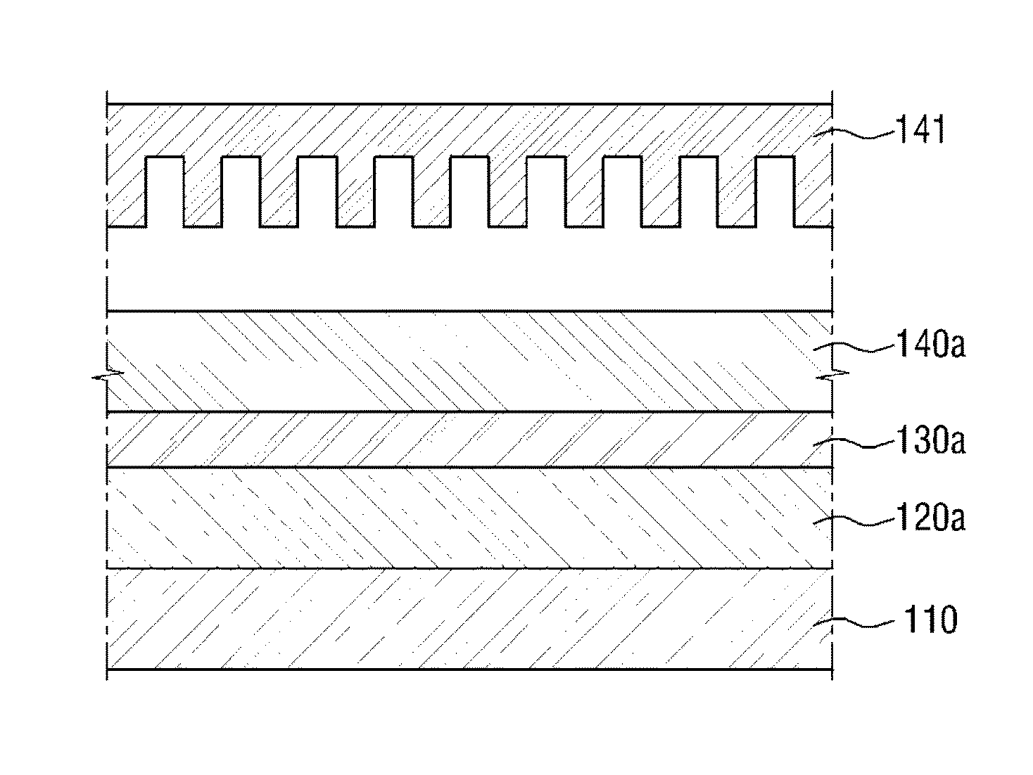
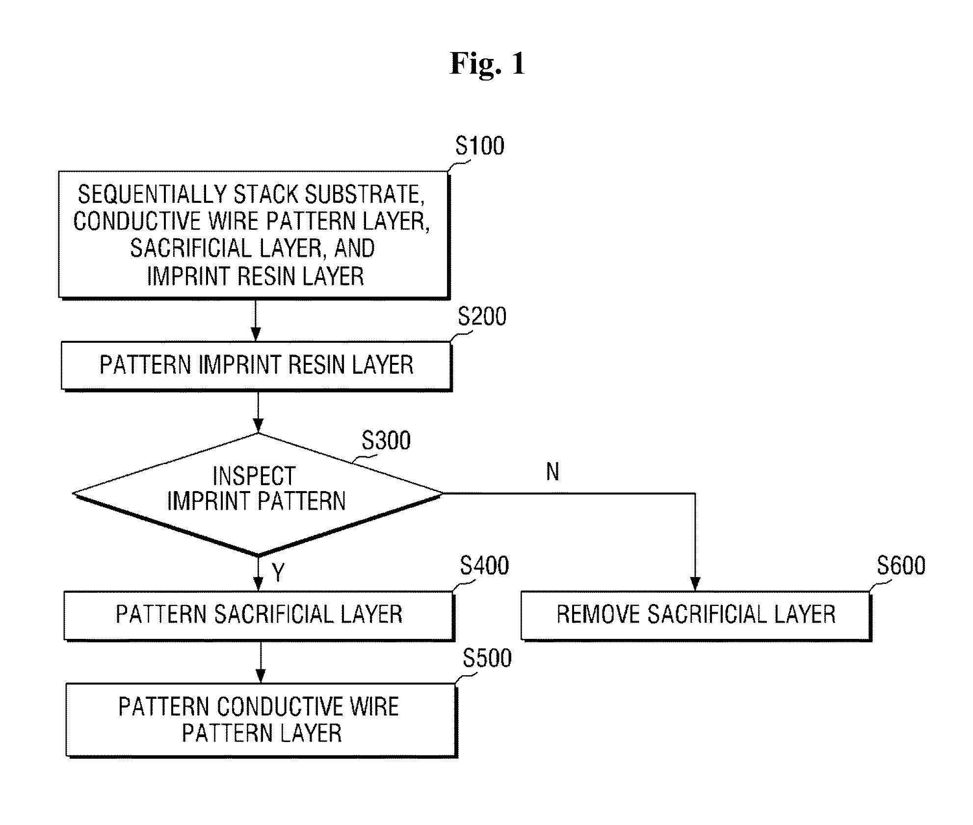
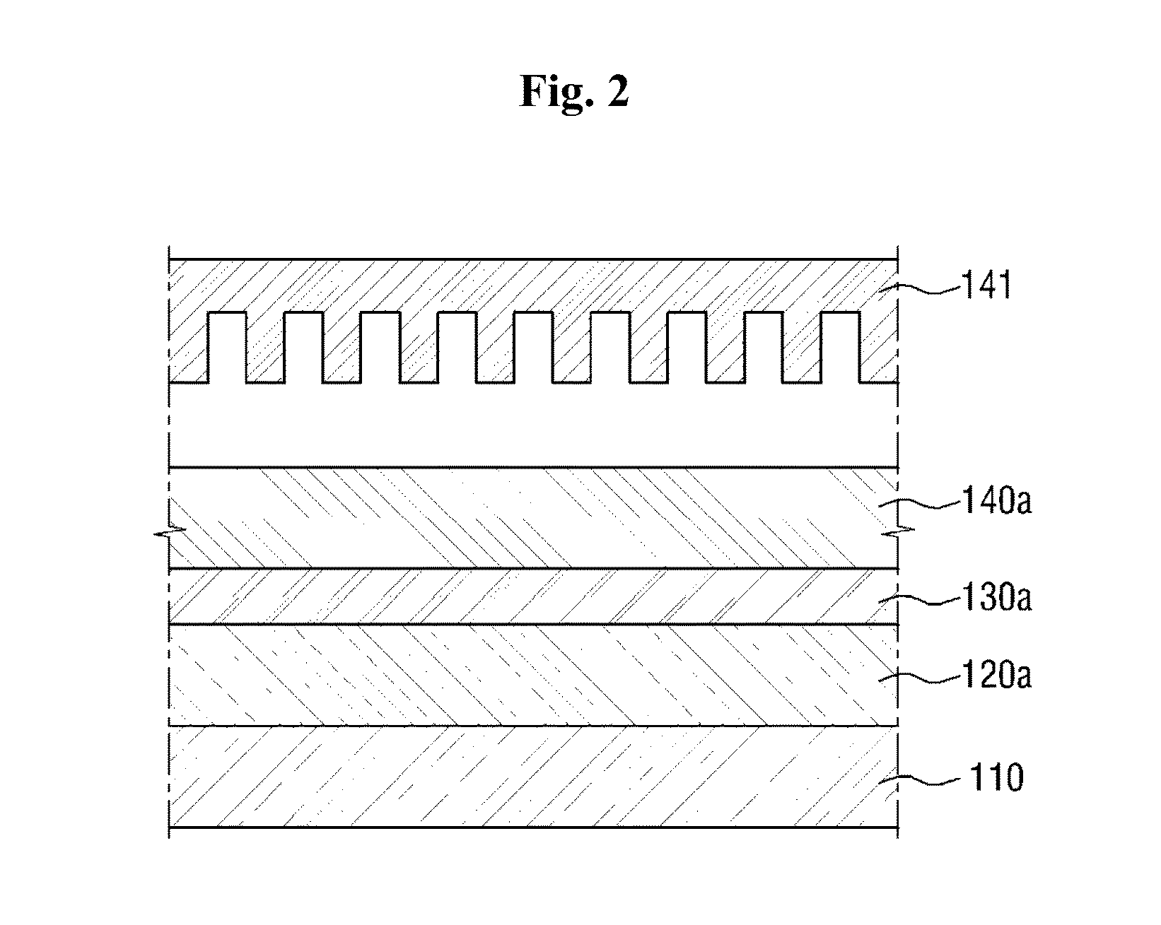
The present invention provides a wire grid polarizer with improved optical properties, a display device including the same, and a method of fabricating them. The method includes sequentially stacking a conductive wire pattern layer, a sacrificial layer, and an imprint pattern layer, patterning the imprint pattern layer, and inspecting it for faults. If a fault is present, the sacrificial layer is removed from the conductive wire pattern layer. The wire grid polarizer includes a substrate and a conductive wire pattern disposed on the substrate, and a sacrificial layer pattern disposed on the conductive wire patterns. The sacrificial layer pattern is formed of at least one of polyimide, an organic-inorganic hybrid material, and silicon. The display device includes a wire grid polarizer having a substrate, a plurality of parallel conductive wire patterns on the substrate, and a plurality of sacrificial layer patterns on the conductive wire patterns.

Problems solved by technology

However, when foreign materials, not air, flow into a space between wire patterns, polarization efficiency deteriorates, and when a material having a higher refractive index than that of air flows in, transmittance and an extinction ratio are degraded in a visual ray region.

Method used


Image

  • Wire grid polarizer and method of fabricating the same
  • Wire grid polarizer and method of fabricating the same
  • Wire grid polarizer and method of fabricating the same

Examples


Embodiment Construction

[0022]The invention is described more fully hereinafter with reference to the accompanying drawings, in which embodiments of the invention are shown. This invention may, however, be embodied in many different forms and should not be construed as limited to the embodiments set forth herein. Rather, these embodiments are provided so that this disclosure is thorough, and will fully convey the scope of the invention to those skilled in the art. It will be understood that for the purposes of this disclosure, “at least one of X, Y, and Z” can be construed as X only, Y only, Z only, or any combination of two or more items X, Y, and Z (e.g., XYZ, XZ, XYY, YZ, ZZ). Throughout the drawings and the detailed description, unless otherwise described, the same drawing reference numerals are understood to refer to the same elements, features, and structures. The relative size and depiction of these elements may be exaggerated for clarity.

[0023]The terminology used herein is for the purpose of descr...


PUM


Abstract

A method of fabricating a wire grid polarizer includes sequentially stacking a conductive wire pattern layer, a sacrificial layer, and an imprint pattern layer; patterning the imprint pattern layer; inspecting the patterned imprint pattern layer for a fault; and removing the sacrificial layer from the conductive wire pattern layer if the fault is present on the patterned imprint pattern layer.

Description

CROSS-REFERENCE TO RELATED APPLICATION[0001]This application claims priority from and the benefit under 35 U.S.C. §119(a) of Korean Patent Application No. 10-2014-0121126 filed on Sep. 12, 2014, the entire disclosure of which is incorporated herein by reference for all purposes.BACKGROUND[0002]1. Field[0003]The following description relates to a wire grid polarizer and a method of fabricating the same.[0004]2. Discussion of the Background[0005]A parallel conductive wire array, in which parallel conductive lines are arranged in order to polarize specific polarized light in an electromagnetic wave, is generally referred to as a wire grid.[0006]A wire grid structure having a shorter period than that of a wavelength of corresponding light has a polarization property of reflecting polarized light in a direction of a wire and allowing polarized light vertical to the direction of the wire to pass through for depolarized incident light. This has an advantage in that reflected polarized ligh...

Claims


Application Information

Patent Timeline
IPC IPC(8): G02B5/30
CPCG02B5/3058G02F1/133548
Inventor TAKAKUWA, ATSUSHI
Owner SAMSUNG DISPLAY CO LTD
Learn More