

Light source apparatus
- Summary
- Abstract
- Description
- Claims
- Application Information
AI Technical Summary
Benefits of technology
Problems solved by technology
Method used
Image

Examples
first embodiment
[0033][Configuration]
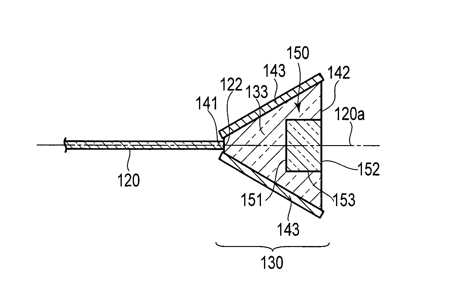
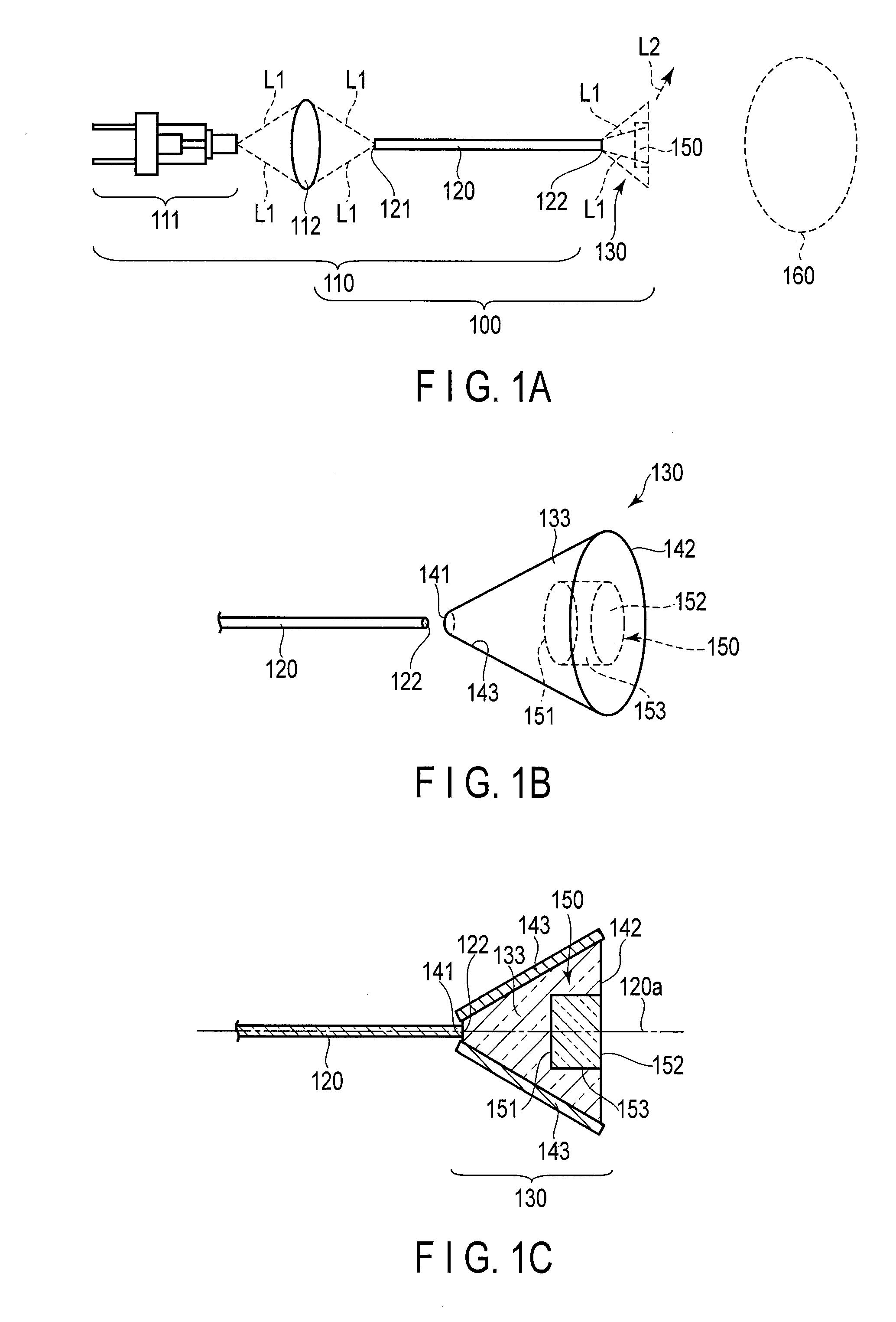
[0034]The first embodiment will be described with reference to FIGS. 1A, 1B, and 1C. In FIGS. 1A and 1B, the illustration of a portion of members is omitted. In FIG. 1B, a light guiding member 120 and an incidence portion 141 of a light diffusing unit 130 are shown with a space therebetween.
[0035][Light Source Apparatus 100]
[0036]The light source apparatus 100 mainly includes a primary light source 110 and the light diffusing unit 130. The light source apparatus 100 is configured to irradiate a diffusing member 150 disposed inside the light diffusing unit 130 with primary light L1 emitted from the primary light source 110. Next, a detailed structure of each unit will be described.
[0037][Primary Light Source 110]
[0038]The primary light source 110 includes a semiconductor laser light source 111 that emits the primary light L1, a condenser lens 112 that condenses the primary light L1 emitted from the semiconductor laser light source 111, and the light guiding membe...
second embodiment
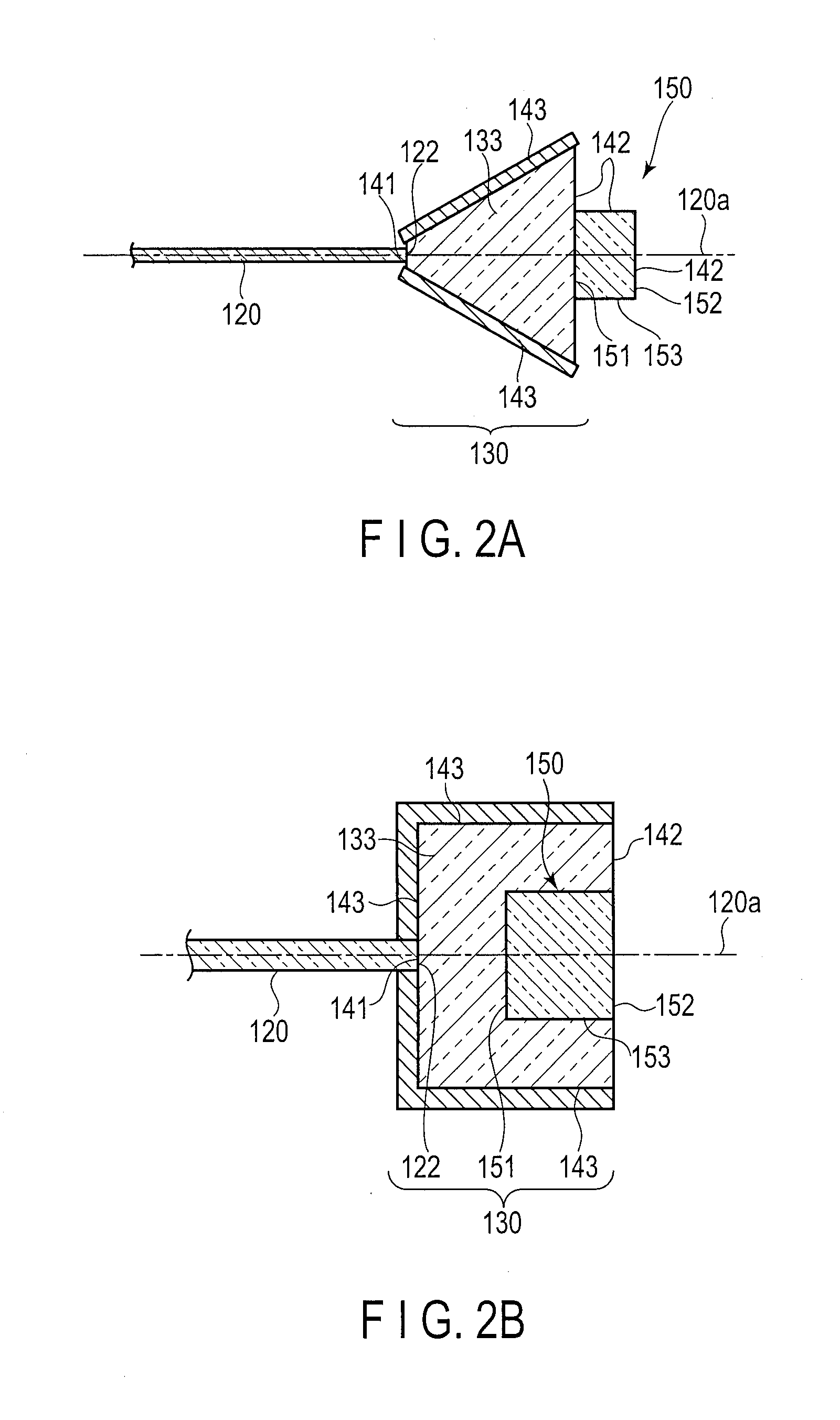
[0097][Configuration]
[0098]The second embodiment will be described with reference to FIGS. 3A, 3B, 3C, 3D, and 3E. In FIGS. 3A and 3B, the illustration of a portion of members is omitted. In FIG. 3B, a light guiding member 120 and an incidence portion 141 of a light diffusing unit 130 are shown with a space therebetween.
[0099][Light Source Apparatus 100, Primary Light Source 110]
[0100]A Light source apparatus 100 and a primary light source 110 are configured in the same manner as in the first embodiment.
[0101][Light Diffusing Unit 130]
[0102]The light diffusing unit 130 includes the incidence portion 141 on which primary light L1 emitted from a primary light emission end 122 is incident and an emission portion 142 having a function to emit desired illumination light to an external irradiation object 160. The light diffusing unit 130 also includes a reflection diffusing member 150 as a first optical function member and a light transmission member 133 as a third optical function member...
third embodiment
[0151][Configuration]
[0152]FIG. 5A shows a light diffusing unit 130 according to the third embodiment.
[0153]In the second embodiment, the first optical function member directly irradiated by the primary light L1 is the reflection diffusing member 150, the second optical function member is the regular reflection portion 145 formed on the taper surface of the light transmission member 133, and the third optical function member is the light transmission member 133 disposed between the diffusing member 150 and the regular reflection portion 145.
[0154]In the present embodiment, however, the first optical function member is a regular reflection portion 250 and the second optical function member is a reflection diffusing member 243 and these points are different from the second embodiment.
[0155]The regular reflection portion 250 in the present embodiment is formed by a top surface of a base material being coated with a reflecting surface made of metal. The regular reflection portion 250 is...
PUM
 Abstract
Description
Claims
Application Information