

Inkjet print head
a technology inkjet printing, which is applied in the direction of printing and inking apparatus, etc., can solve the problems of degrading the discharge efficiency of inkjet print head, not revealing any configuration, and reducing the discharge performance of inkjet print head, so as to improve the discharge efficiency of ink and facilitate the circulation of ink
- Summary
- Abstract
- Description
- Claims
- Application Information
AI Technical Summary
Benefits of technology
Problems solved by technology
Method used
Image

Examples
first embodiment
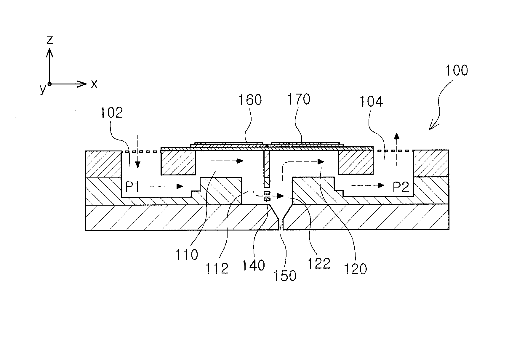
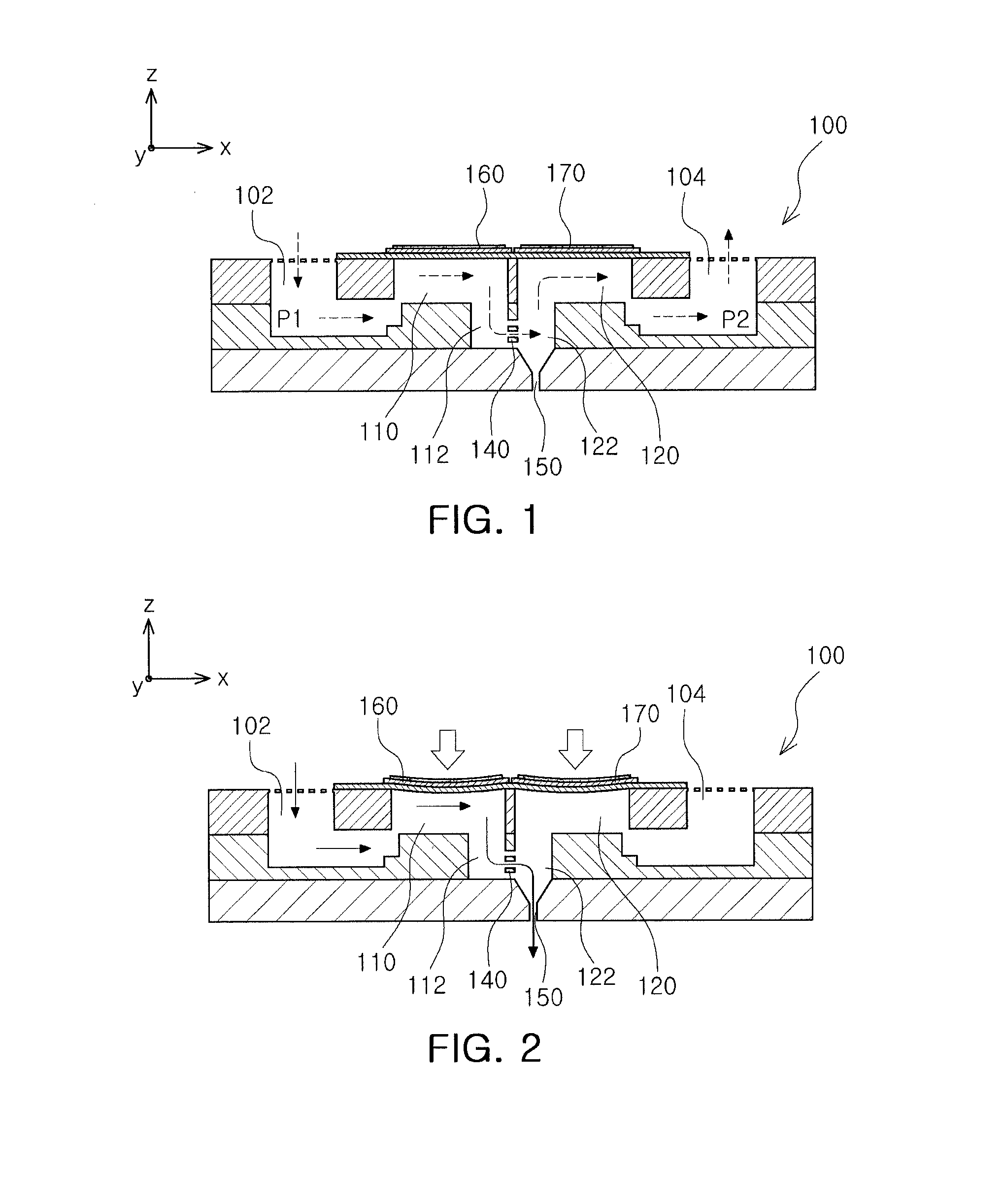
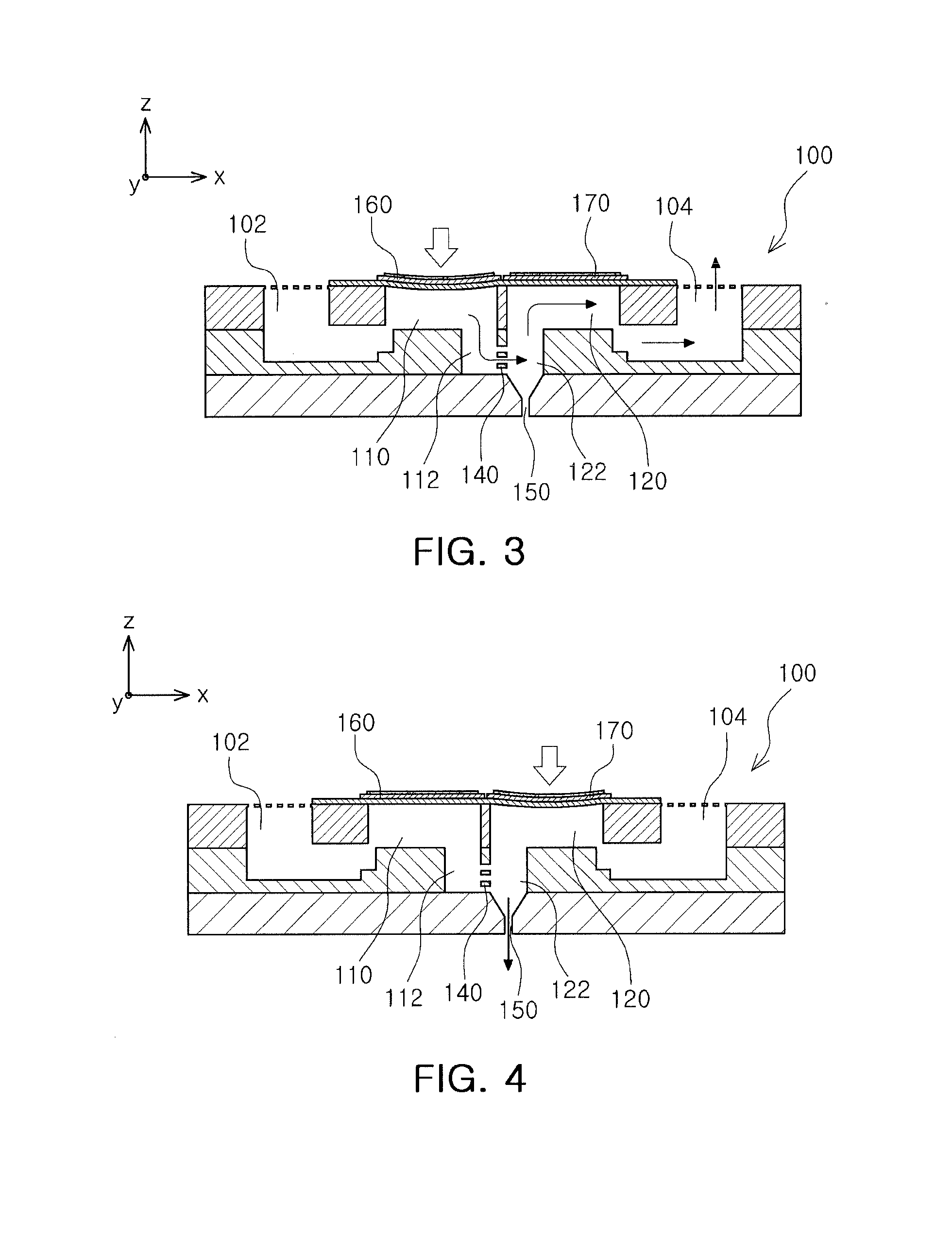
[0042]An inkjet print head according to the present invention will be described with reference to FIG. 1.
[0043]An inkjet print head 100 according to the first embodiment of the present invention may include a first common channel 102, a second common channel 104, a first pressure chamber 110, a second pressure chamber 120, a connection channel 140, and a nozzle 150. In addition, the inkjet print head 100 may include a first actuator 160 and a second actuator 170.
[0044]The first common channel 102 may be elongated in a first direction (a Y axis direction of FIG. 1) of the inkjet print head 100. The first common channel 102 formed as described above may be connected to an ink supplying part in which ink is stored. Therefore, the ink may be continuously supplied through the first common channel 102.
[0045]The first common channel 102 may have a first pressure P1 having a predetermined level formed therein. The first pressure P1 may be higher than atmospheric pressure. In addition, the f...
second embodiment
[0083]An inkjet print head according to the present invention will be described with reference to FIG. 8.
[0084]The inkjet print head 100 according to the second embodiment of the present invention may be distinguished from that of the first embodiment in that the first pressure chamber 110 and the second pressure chamber 120 have different volumes.
[0085]In order to smoothly move the ink from the first common channel 102 to the second common channel 104, the first pressure chamber 110 needs to have a higher pressure than that of the second pressure chamber 120. In consideration of this fact, according to the present embodiment, the first pressure chamber 110 may be formed to have a volume V1 larger than a volume V2 of the second pressure chamber 120.
[0086]In the inkjet print head 100 configured as described above, the volume V1 of the first pressure chamber 110 is larger than the volume V2 of the second pressure chamber 120, whereby the pressure of the first pressure chamber 110 may ...
third embodiment
[0087]An inkjet print head according to the present invention will be described with reference to FIG. 9.
[0088]The inkjet print head 100 according to the third embodiment of the present invention may be distinguished from those of the above described embodiments in that the first actuator 160 and the second actuator 170 have different sizes. More specifically, the first actuator 160 may be larger than the second actuator 170. For example, the first actuator 160 may be longer than the second actuator 170 or may have driving force greater than that of the second actuator 170.
[0089]In the inkjet print head 100 configured as described above, the pressure formed in the first pressure chamber 110 is higher than the pressure formed in the second pressure chamber 120 when the actuators 160 and 170 are operated, whereby the ink may be effectively moved from the first pressure chamber 110 to the second pressure chamber 120.
PUM
 Abstract
Description
Claims
Application Information