


Quick Research
Generate reliable direction feasibility study reports for your R&D in just a few steps.

Technical Q&A
Discover and master advanced knowledge NOW. Basics, ideas, possibilities, all at once.

Find Solutions
As an expert in R&D theories, this can generate solutions to your technical problems instantly.

Evaluate Feasibility
Analyze your overall solution with one click, know your potential R&D risks in advance.

Monitor Landscape
Get weekly tech updates, stay abreast of the latest tech innovations and key insights.
Inkjet print head
a technology inkjet printing, which is applied in the direction of printing and inking apparatus, etc., can solve the problems of degrading the discharge efficiency of inkjet print head, not revealing any configuration, and reducing the discharge performance of inkjet print head, so as to improve the discharge efficiency of ink and facilitate the circulation of ink
- Summary
- Abstract
- Description
- Claims
- Application Information
AI Technical Summary
Benefits of technology
Problems solved by technology
Method used
Image

Examples
first embodiment
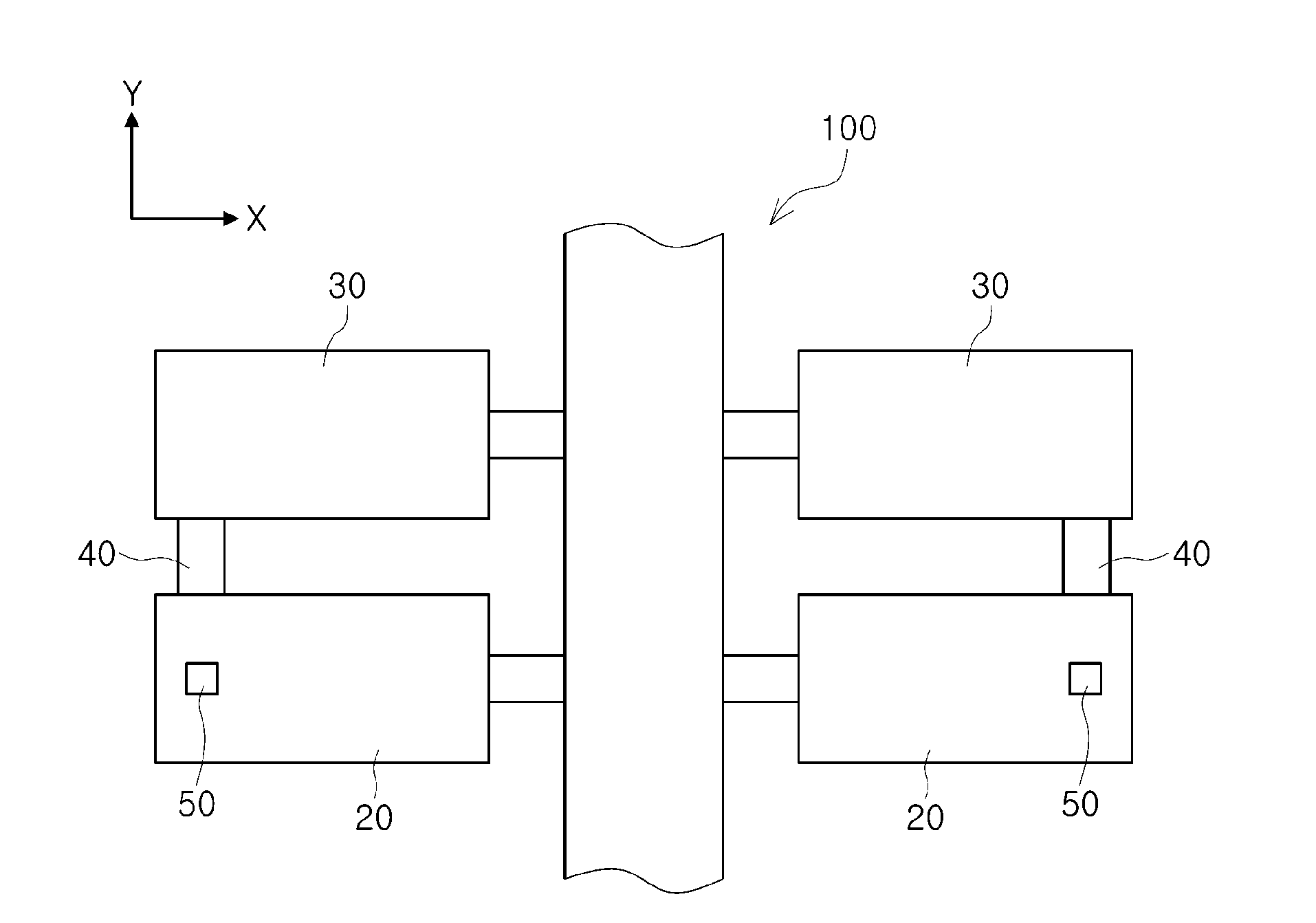
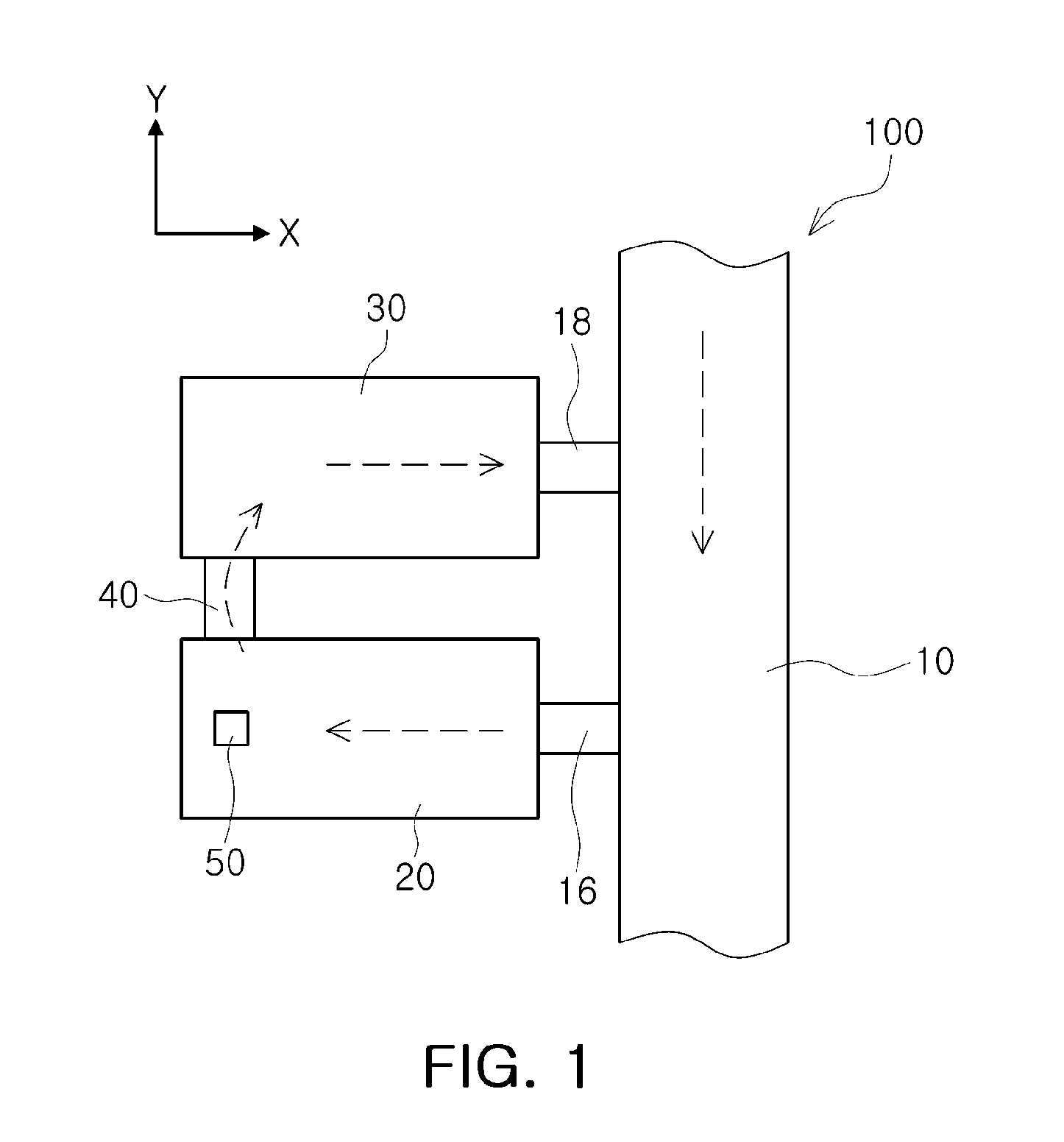
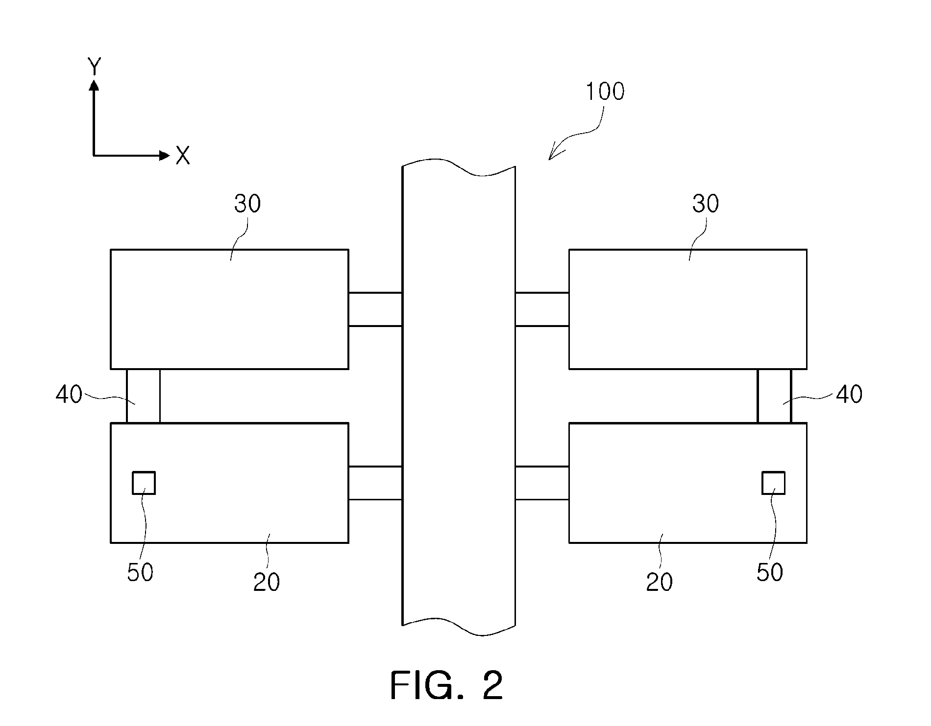
[0051]The configuration of an inkjet print head according to the present invention will be described with reference to FIGS. 1 and 2.
[0052]An inkjet print head 100 according to the first embodiment of the present invention may include a common channel 10, a first pressure chamber 20, a second pressure chamber 30, and a connection channel 40.
[0053]The common channel 10 may be elongated in a first direction (a Y axis direction of FIG. 1) of the inkjet print head 100. The common channel 10 formed as described above may be connected to an ink supplying part and supply ink stored in the ink supplying part to one or more pressure chambers.
[0054]The first pressure chamber 20 may be formed on one side of the common channel 10 and may be connected to the common channel 10. Here, the first pressure chamber 20 and the common channel 10 may be connected to each other by a restrictor 16.
[0055]The first pressure chamber 20 may be provided with a nozzle 50. The nozzle 50 may have a predetermined s...
second embodiment
[0078]An inkjet print head according to the present invention will be described with reference to FIGS. 9 and 10.
[0079]The inkjet print head 100 according to the second embodiment of the present invention may be distinguished from that of the first embodiment by a connected structure of the first pressure chamber 20 and the second pressure chamber 30 therebetween.
[0080]In the present embodiment, the first pressure chamber 20 and the second pressure chamber 30 may be connected by a first connection channel 42 and a second connection channel 44. More specifically, the first connection channel 42 may connect between one end of the first pressure chamber 20 and one end of the second pressure chamber 30, and the second connection channel 44 may connect between the other end of the first pressure chamber 20 and the other end of the second pressure chamber 30. Here, the ink may flow from the first pressure chamber 20 to the second pressure chamber 30 through the first connection channel 42...
third embodiment
[0090]An inkjet print head according to the present invention will be described with reference to FIGS. 11 through 15.
[0091]The inkjet print head 100 according to the third embodiment of the present invention may be distinguished from the above-described embodiments in that it includes a plurality of common channels. That is, the inkjet print head 100 according to the third embodiment of the present invention may be distinguished from the above-described embodiments in that it forms a structure of circulating the ink through the plurality of common channels.
[0092]The inkjet print head 100 may include the first substrate 110, the second substrate 120, the third substrate 130, and the vibration plate 140. However, the number of substrates configuring the inkjet print head 100 is not limited thereto, but may be increased or decreased as necessary. For example, the inkjet print head 100 may be configured of two substrates and one vibration plate 140 or may be configured of four substrat...
PUM
 Abstract
Description
Claims
Application Information
 - R&D Engineer
- R&D Manager
- IP Professional
- Industry Leading Data Capabilities
- Powerful AI technology
- Patent DNA Extraction
Browse by: Latest US Patents, China's latest patents, Technical Efficacy Thesaurus, Application Domain, Technology Topic, Popular Technical Reports.
© 2024 PatSnap. All rights reserved.Legal|Privacy policy|Modern Slavery Act Transparency Statement|Sitemap|About US| Contact US: help@patsnap.com