Position Detection Apparatus and Image Display Apparatus

Inactive Publication Date: 2014-03-20
FUNAI ELECTRIC CO LTD
View PDF4 Cites 10 Cited by
  • Summary
  • Abstract
  • Description
  • Claims
  • Application Information

AI Technical Summary

Benefits of technology

[0027]In the image display apparatus according to the second aspect of the present invention, as hereinabove described, when the indicator such as an implement such as a pointer or the finger of a user indicates a part of the projection image, the position of the indicator on a plane parallel to the projection surface can be detected on the basis of the scan timing and the timing of receiving the reflected laser beam by the light receiving portions, and these light receiving portions are arranged at the different heights from the projection surface, so that the determination portion can determine a position in the projection image indicated by the indicator in the plane parallel to the projection surface and in the height direction orthogonal to the projection surface on the basis of the detection results of these light receiving portions. Thus, the three-dimensional position of the indicator with respect to the projection image can be detected. Furthermore, according to where the indicator is located with respect to the projection image having a certain width, aberration is generated in the reflected laser beam guided to the light receiving portions by the lens. For example, the spot diameter of the reflected laser beam guided by the lens on the light receiving portions becomes larger when the indicator is located at an end of the projection image than when th

Problems solved by technology

Furthermore, according to where the indicator is located with respect to the projection image having a certain

Method used


Image

  • Position Detection Apparatus and Image Display Apparatus
  • Position Detection Apparatus and Image Display Apparatus
  • Position Detection Apparatus and Image Display Apparatus

Examples


Embodiment Construction

[0048]An embodiment of the present invention is hereinafter described with reference to the drawings.

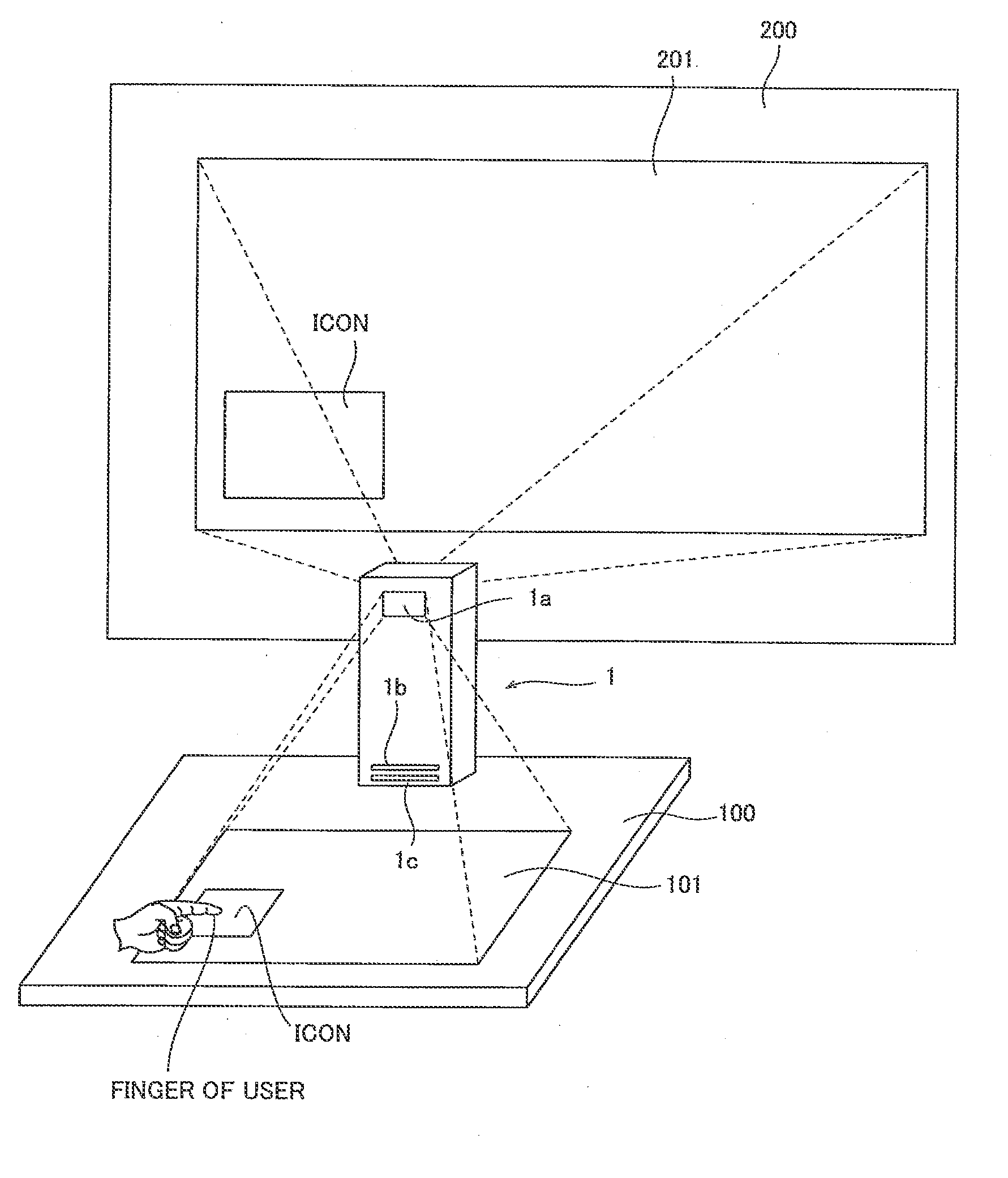
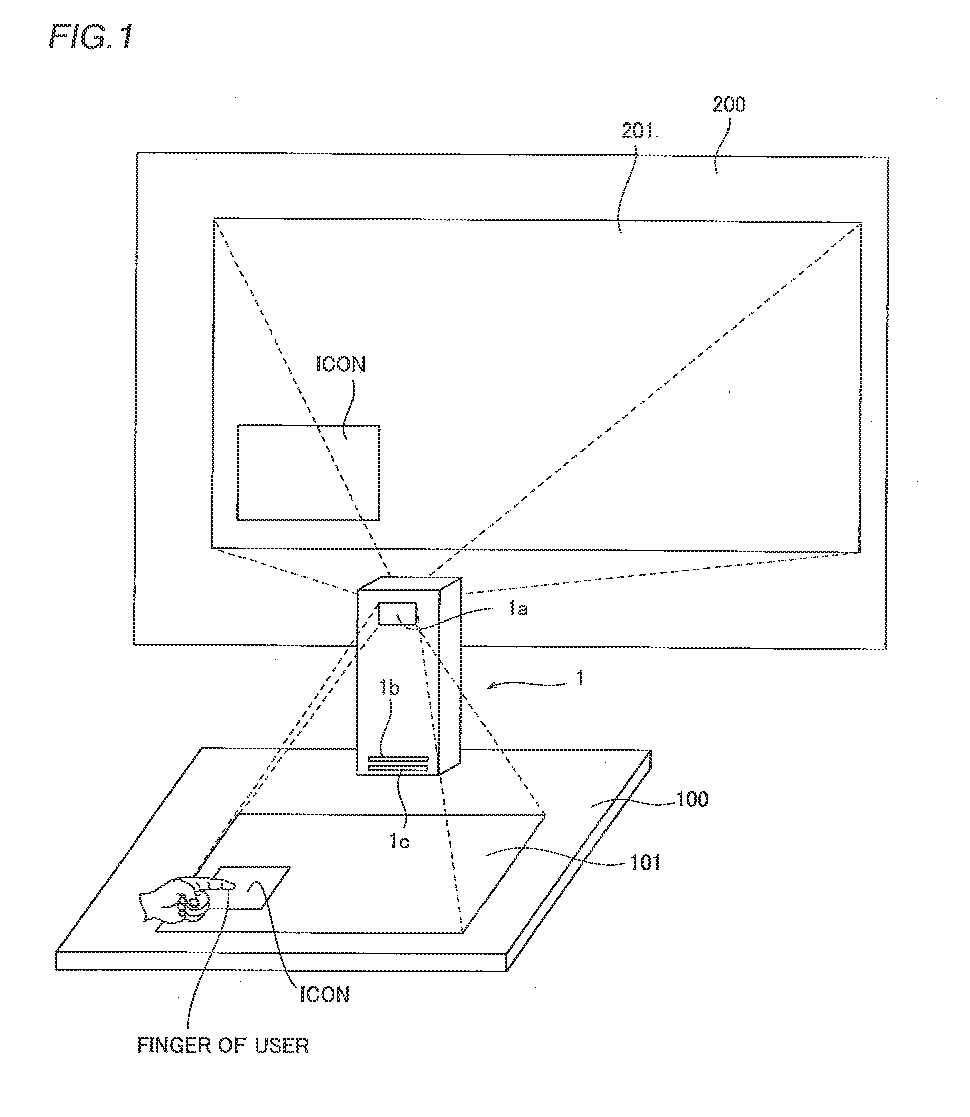
[0049]FIG. 1 illustrates a laser projector 1 according to the embodiment of the present invention. This laser projector 1 incorporates a position detection apparatus according to the embodiment of the present invention. The laser projector 1 according to this embodiment is set on a table 100, for example, projects and displays the same image projected by scanning a laser beam as a display image 201 on a projection surface 200 such as a screen, and projects and displays the image as an operation image 101 on a projection surface such as the upper surface of the table 100. In an example shown in the figure, a laser beam is emitted from a window 1a of a projector housing provided on the side opposite to the side of the projector housing from which the display image 201 is projected, whereby the operation image 101 is projected. The laser projector 1 is an example of the “image display a...


PUM


Abstract

This position detection apparatus includes a plurality of light receiving portions receiving a reflected laser beam from an indicator, a lens, a masking portion arranged between the light receiving portions and the lens, having a masking surface restricting the reflected laser beam guided to the light receiving portions in a direction orthogonal to a projection surface, and a determination portion determining a three-dimensional position in a projection image indicated by the indicator. The masking surface of the masking portion has such a concave shape that opposing ends thereof are closer to the lens than a central portion thereof.

Description

BACKGROUND OF THE INVENTION[0001]1. Field of the Invention[0002]The present invention relates to an image display apparatus projecting an image with a laser beam and a position detection apparatus detecting the position of an indicator with respect to a projection image.[0003]2. Description of the Background Art[0004]An image display apparatus, such as a laser projector, projecting an image on a projection surface with a laser beam is put to practical use. In such an image display apparatus, a technology to detect a position in a projection image pointed by a user is known.[0005]Japanese Patent Laying-Open No. 2009-258569 discloses an electronic device scanning a beam from an infrared laser by a part of a MEMS mirror of a projector module, rendering the beam parallel to an installation surface by a reflective mirror, and making the infrared beam reflected from a finger incident on a photodiode by a beam splitter when the finger touches a prescribed area of a projection image to meas...

Claims


Application Information

Patent Timeline
IPC IPC(8): G01B11/14
CPCG01B11/14G06F3/0304G06F2203/04101G06F3/0421G06F3/042G06F3/0425G06F3/0486H04N9/3129H04N9/3147G06F2203/04108G02B26/101G02B27/104G02B27/141G06F3/03G06F3/041
Inventor HIRAI, TOMOHISA
Owner FUNAI ELECTRIC CO LTD
Why Eureka
Try Eureka