

Imaging lens
a technology of imaging lens and optical fiber, applied in the field of imaging lens, can solve problems such as difficult performance implementation, and achieve the effect of excellent optical characteristics
- Summary
- Abstract
- Description
- Claims
- Application Information
AI Technical Summary
Benefits of technology
Problems solved by technology
Method used
Image

Examples
first preferred embodiment
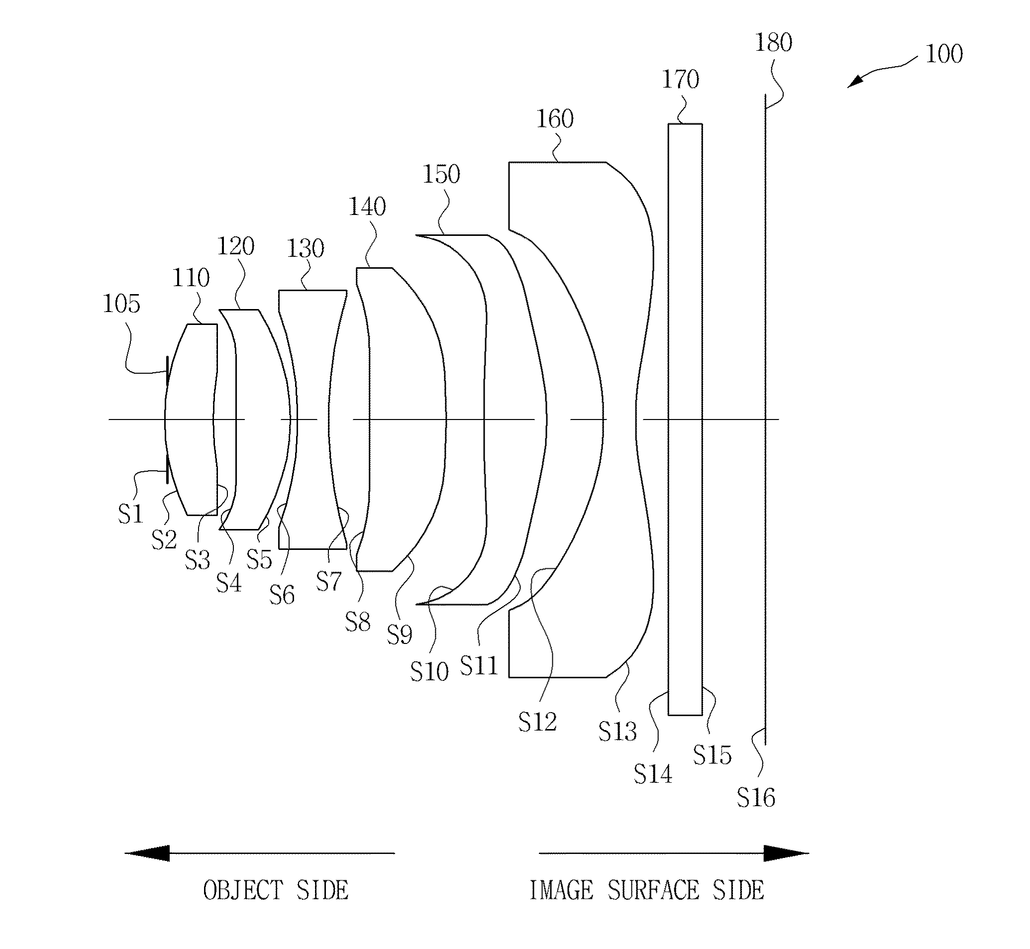
[0089]FIG. 1 is a lateral cross-sectional view schematically showing an internal structure of an imaging lens according to a first preferred embodiment of the present invention.
[0090]Referring to FIG. 1, the imaging lens 100 according to the first preferred embodiment of the present invention is configured to include a first lens 110, a second lens 120, a third lens 130, a fourth lens 140, a fifth lens 150, and a sixth lens 160 sequentially disposed from an object side. In addition, the imaging lens 100 according to the first preferred embodiment of the present invention may further include an aperture stop 105 positioned to be closer to the object side or an image surface side as compared with any one of the first to sixth lenses 110 and 160.
[0091]First, in order to obtain an image of the object (subject), light corresponding to image information of the object sequentially passes through the first lens 110, the aperture stop 105, the second lens 120, the third lens 130, the fourth ...
second preferred embodiment
[0168]FIG. 4 is a lateral cross-sectional view schematically showing an internal structure of an imaging lens according to a second preferred embodiment of the present invention.
[0169]Referring to FIG. 4, the imaging lens 200 according to the second preferred embodiment of the present invention is configured to include a first lens 210, a second lens 220, a third lens 230, a fourth lens 240, a fifth lens 250, and a sixth lens 260 sequentially disposed from an object side. In addition, the imaging lens 200 according to the second preferred embodiment of the present invention may further include an aperture stop 205 positioned to be closer to the object side or an image surface side as compared with any one of the first to sixth lenses 210 and 260.
[0170]First, in order to obtain an image of the object (subject), light corresponding to image information of the object sequentially passes through the first lens 210, the aperture stop 205, the second lens 220, the third lens 230, the four...
third referred embodiment
[0240]FIG. 7 is a lateral cross-sectional view schematically showing an internal structure of an imaging lens according to a third preferred embodiment of the present invention.
[0241]Referring to FIG. 7, the imaging lens 300 according to the third preferred embodiment of the present invention is configured to include a first lens 310, a second lens 320, a third lens 330, a fourth lens 340, a fifth lens 350, and a sixth lens 360 sequentially disposed from an object side. In addition, the imaging lens 300 according to the third preferred embodiment of the present invention may further include an aperture stop 305 positioned to be closer to the object side or an image surface side as compared with any one of the first to sixth lenses 310 and 360.
[0242]First, in order to obtain an image of the object (subject), light corresponding to image information of the object sequentially passes through the first lens 310, the aperture stop 305, the second lens 320, the third lens 330, the fourth ...
PUM
 Abstract
Description
Claims
Application Information